A magnetic bearing is a type of bearing that supports a load using magnetic levitation. Magnetic bearings support moving parts without physical contact. For instance, they are able to levitate a rotating shaft and permit relative motion with very low friction and no mechanical wear. Magnetic bearings support the highest speeds of any kind of bearing and have no maximum relative speed.
Active bearings have several advantages: they do not suffer from wear, have low friction, and can often accommodate irregularities in the mass distribution automatically, allowing rotors to spin around their center of mass with very low vibration.
Passive magnetic bearings use permanent magnets and, therefore, do not require any input power but are difficult to design due to the limitations described by Earnshaw's theorem. Techniques using diamagnetic materials are relatively undeveloped and strongly depend on material characteristics. As a result, most magnetic bearings are active magnetic bearings, using electromagnets which require continuous power input and an active control system to keep the load stable. In a combined design, permanent magnets are often used to carry the static load and the active magnetic bearing is used when the levitated object deviates from its optimum position. Magnetic bearings typically require a back-up bearing in the case of power or control system failure.
The hardware consists of an electromagnet assembly, a set of power amplifiers which supply current to the electromagnets, a controller, and gap sensors with associated electronics to provide the feedback required to control the position of the rotor within the gap. The power amplifier supplies equal bias current to two pairs of electromagnets on opposite sides of a rotor. This constant tug-of-war is mediated by the controller, which offsets the bias current by equal and opposite perturbations of current as the rotor deviates from its center position.
The gap sensors are usually inductive in nature and sense in a differential mode. The power amplifiers in a modern commercial application are solid state devices which operate in a pulse-width modulation configuration. The controller is usually a microprocessor or digital signal processor.
Two types of instabilities are typically present in magnetic bearings. Attractive magnets produce an unstable static force that decreases with increasing distance and increases at decreasing distances. This can cause the bearing to become unbalanced. Secondly, because magnetism is a conservative force, it provides little damping; oscillations may cause loss of successful suspension if any driving forces are present.
History
The table below lists several early patents for active magnetic bearings. Earlier patents for magnetic suspensions can be found but are excluded here because they consist of assemblies of permanent magnets of problematic stability per Earnshaw's Theorem.
Early U.S. patents in active magnetic bearings
Inventor(s)
Year
Patent number
Title
Beams, Holmes
1941
2,256,937
Suspension of Rotatable Bodies
Beams
1954
2,691,306
Magnetically Supported Rotating Bodies
Gilbert
1955
2,946,930
Magnetic suspension
Beams
1962
3,041,482
Apparatus for Rotating Freely Suspended Bodies
Beams
1965
3,196,694
Magnetic Suspension System
Wolf
1967
3,316,032
Poly-Phase Magnetic Suspension Transformer
Boden et al.
1968
DE1750602
Magnetische Lagerung (German patent)
Lyman
1971
3,565,495
Magnetic Suspension Apparatus
Habermann
1973
3,731,984
Magnetic Bearing Block Device for Supporting a Vertical Shaft Adapted for Rotating at High Speed
Habermann, Loyen, Joli, Aubert
1974
3,787,100
Devices Including Rotating Members Supported by Magnetic Bearings
Habermann, Brunet
1977
4,012,083
Magnetic Bearings
Habermann, Brunet, LeClére
1978
4,114,960
Radial Displacement Detector Device for a Magnetic Bearings
Croot, Estelle
1990
1,988,024,350
Further Improvements in Magnetic Bearings
Meeks, Crawford R
1992
5,111,102
Magnetic Bearing Structure
Croot, Estelle
1994
1,991,075,982
Non-linear Magnetic Bearing
Jesse Beams from the University of Virginia filed some of the earliest active magnetic bearing patents[12][13] during World War II. The patents dealt with ultracentrifuges intended for the enrichment of isotopes of elements needed for the Manhattan Project. However, magnetic bearings did not mature until advances in solid-state electronics and modern computer-based control technology with the work of Habermann[14] and Schweitzer.[15] In 1987, Estelle Croot further improved active magnetic bearing technology,[16] but these designs were not manufactured due to expensive costs of production, which used a laser guidance system. Estelle Croot's research was the subject of three Australian patents and was funded by Nachi Fujikoshi, Nippon Seiko KK and Hitachi, and her calculations were used in other technologies that used rare-earth magnets but the active magnetic bearings were only developed to the prototype stage. Croot's[17] design also included an advance computerised control system, while the last design was a non-linear magnetic bearing.
Kasarda[18] reviews the history of active magnetic bearings in depth. She notes that the first commercial application of active magnetic bearings was in turbomachinery. The active magnetic bearing allowed the elimination of oil reservoirs on compressors for the NOVA Gas Transmission Ltd. (NGTL) gas pipelines in Alberta, Canada. This reduced the fire hazard allowing a substantial reduction in insurance costs. The success of these magnetic bearing installations led NGTL to pioneer the research and development of a digital magnetic bearing control system as a replacement for the analog control systems supplied by the American company Magnetic Bearings Inc. In 1992, NGTL's magnetic bearing research group formed the company Revolve Technologies Inc. for commercializing the digital magnetic bearing technology. The company was later purchased by SKF of Sweden. The French company S2M, founded in 1976, was the first to commercially market active magnetic bearings. Extensive research on magnetic bearings continues at the University of Virginia in the Rotating Machinery and Controls Industrial Research Program .
During the decade starting in 1996, the Dutch oil-and-gas company NAM installed twenty gas compressors, each driven by a 23-megawatt variable-speed-drive electric motor. Each unit was fully equipped with active magnetic bearings on both the motor and the compressor. These compressors are used in the Groningen gas field to extract the remaining gas from this large gas field and to increase the field capacity. The motor-compressor design was done by Siemens and the active magnetic bearings were delivered by Waukesha Bearings (owned by Dover Corporation). (Originally these bearings were designed by Glacier, this company was later taken over by Federal Mogul and is now part of Waukesha Bearings.) By using active magnetic bearings and a direct drive between motor and compressor (without having a gearbox in between) and by applying dry gas seals, a fully dry-dry (oil-free) system was achieved. Applying active magnetic bearings in both the driver and in the compressor (compared to the traditional configuration using gears and ball bearings) results in a relatively simple system with a very wide operating range and high efficiencies, particularly at partial load. As was done in the Groningen field, the full installation can additionally be placed outdoors without the need for a large compressor building.
Non-contacting permanent magnet bearings with electromotive stabilisation were applied for patent by R. G. Gilbert in 1955 (U. S. Patent 2,946,930) [19] and K. Boden, D. Scheffer in 1968 (German Patent 1750602).[20] These inventions provide the technological basis for a number of practical applications, some of which have reached the stage of industrial series production under licence from Forschungszentrum Jülich since about 1980.[21][22]
Meeks[23] pioneered hybrid magnetic bearing designs (US patent 5,111,102) in which permanent magnets provide the bias field and active control coils are used for stability and dynamic control. These designs using permanent magnets for bias fields are smaller and of lighter weight than purely electromagnetic bearings. The electronic control system is also smaller and requires less electrical power because the bias field is provided by the permanent magnets.
As the development of the necessary components progressed, scientific interest in the field also increased, peaking in the first International Symposium on Magnetic Bearings held in 1988 in Zürich with the founding of the International Society of Magnetic Bearings by Prof. Schweitzer (ETHZ), Prof. Allaire (University of Virginia), and Prof. Okada (Ibaraki University). Since then, the symposium has developed into a biennial conference series with a permanent portal on magnetic bearing technology where all symposium contributions are made available. The web portal is supported by the international research and industrial community. Joining the hall of fame and earning lifetime achievement awards in 2012 were Prof. Yohji Okada, Prof. Gerhard Schweitzer, and Michael Swann of Waukesha Magnetic Bearings .
Applications
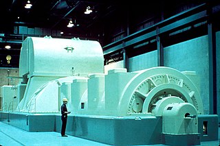
Magnetic bearing advantages include very low and predictable friction, and the ability to run without lubrication and in a vacuum. Magnetic bearings are increasingly used in industrial machines such as compressors, turbines, pumps, motors and generators.
Magnetic bearings are commonly used in watt-hour meters by electric utilities to measure home power consumption. They are also used in energy storage or transportation applications and to support equipment in a vacuum, for example in flywheel energy storage systems.[24][25] A flywheel in a vacuum has very low wind resistance losses, but conventional bearings usually fail quickly in a vacuum due to poor lubrication. Magnetic bearings are also used to support maglev trains in order to get low noise and smooth ride by eliminating physical contact surfaces. Disadvantages include high cost, heavy weight and relatively large size.
Magnetic bearings are also used in some centrifugal compressors for chillers with a shaft made up of magnetic material lies between magnetic bearings. A small amount of current provides magnetic levitation to the shaft which remains freely suspended in air ensuring zero friction between the bearing and the shaft.
Among the most significant industrial applications are turbomolecular pumps for vacuum generation in semiconductor production plants. First commercial magnetic bearing type turbopumps without mechanical stabilisation were marketed by Leybold AG in 1975 (electromagnetic) and in 1989 (permanent magnet based).
In the field of vacuum metrology the spinning rotor gauge (SRG) was introduced as a reference standard by BIPM, Paris 1979. A first laboratory setup of this gauge was established by Jesse Beams in 1946. Commercial series production started in 1980 under licences from Forschungszentrum Jülich. The SRG is significant for vacuum process control in semiconductor manufacturing equipment.
A new application of magnetic bearings is in artificial hearts. The use of magnetic suspension in ventricular assist devices was pioneered by Prof. Paul Allaire and Prof. Houston Wood at the University of Virginia, culminating in the first magnetically suspended ventricular assist centrifugal pump (VAD) in 1999.[citation needed]
Several ventricular assist devices use magnetic bearings, including the LifeFlow heart pump,[26] the DuraHeart Left Ventricular Assist System,[27] the Levitronix CentriMag,[28] and the Berlin Heart.[29] In these devices, the single moving part is suspended by a combination of hydrodynamic force and magnetic force. By eliminating physical contact surfaces, magnetic bearings make it easier to reduce areas of high shear stress (which leads to red blood cell damage) and flow stagnation (which leads to clotting) in these blood pumps.[30] Berlin Heart INCOR was the first commercial ventricular assist device without mechanical or fluid dynamic stabilisation.
Calnetix Technologies, Synchrony Magnetic Bearings (subsidiary of Johnson Controls International), Waukesha Magnetic Bearings, and S2M (subsidiary of SKF) are among the major magnetic bearing developers and manufacturers worldwide.
Future advances
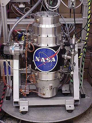
An axial homopolar electrodynamic bearing
With the use of an induction-based levitation system present in maglev technologies such as the Inductrack system, magnetic bearings could replace complex control systems by using Halbach arrays and simple closed loop coils. These systems gain in simplicity, but are less advantageous with regard to eddy current losses. For rotating systems it is possible to use homopolar magnet designs instead of multipole Halbach structures, which reduce losses considerably.
An example that has bypassed the Earnshaw's theorem issues is the homopolar electrodynamic bearing invented by Dr Torbjörn Lembke.[31][32][33] This is a novel type of electromagnetic bearing based on a passive magnetic technology. It does not require any control electronics to operate and works because the electrical currents generated by motion cause a restoring force.[34][35][36]
A linear motor is an electric motor that has had its stator and rotor "unrolled", thus, instead of producing a torque (rotation), it produces a linear force along its length. However, linear motors are not necessarily straight. Characteristically, a linear motor's active section has ends, whereas more conventional motors are arranged as a continuous loop.
An electric motor is an electrical machine that converts electrical energy into mechanical energy. Most electric motors operate through the interaction between the motor's magnetic field and electric current in a wire winding to generate force in the form of torque applied on the motor's shaft. An electric generator is mechanically identical to an electric motor, but operates in reverse, converting mechanical energy into electrical energy.
In electricity generation, a generator is a device that converts motion-based power or fuel-based power into electric power for use in an external circuit. Sources of mechanical energy include steam turbines, gas turbines, water turbines, internal combustion engines, wind turbines and even hand cranks. The first electromagnetic generator, the Faraday disk, was invented in 1831 by British scientist Michael Faraday. Generators provide nearly all the power for electrical grids.
A flywheel is a mechanical device which uses the conservation of angular momentum to store rotational energy; a form of kinetic energy proportional to the product of its moment of inertia and the square of its rotational speed. In particular, assuming the flywheel's moment of inertia is constant then the stored (rotational) energy is directly associated with the square of its rotational speed.
Electrodynamic suspension (EDS) is a form of magnetic levitation in which there are conductors which are exposed to time-varying magnetic fields. This induces eddy currents in the conductors that creates a repulsive magnetic field which holds the two objects apart.
A DC motor is an electrical motor that uses direct current (DC) to produce mechanical force. The most common types rely on magnetic forces produced by currents in the coils. Nearly all types of DC motors have some internal mechanism, either electromechanical or electronic, to periodically change the direction of current in part of the motor.
Inductrack is a passive, fail-safe electrodynamic magnetic levitation system, using only unpowered loops of wire in the track and permanent magnets on the vehicle to achieve magnetic levitation. The track can be in one of two configurations, a "ladder track" and a "laminated track". The ladder track is made of unpowered Litz wire cables, and the laminated track is made out of stacked copper or aluminium sheets.
Maglev is a system of train transportation that is levitated along a guideway through the use of magnetic forces. By levitating, maglev trains remove the rail-to-wheel contact present in conventional railways, eliminating rolling resistance.
Electromagnetic suspension (EMS) is the magnetic levitation of an object achieved by constantly altering the strength of a magnetic field produced by electromagnets using a feedback loop. In most cases the levitation effect is mostly due to permanent magnets as they have no power dissipation, with electromagnets only used to stabilise the effect.
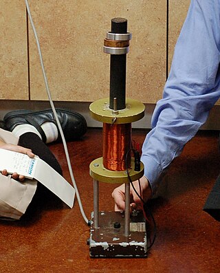
The Mendocino motor is a solar-powered magnetically levitated electric motor. With a very low power output, they are generally used as technical demonstrations only, but are a popular construction project with electronic enthusiasts.
A homopolar generator is a DC electrical generator comprising an electrically conductive disc or cylinder rotating in a plane perpendicular to a uniform static magnetic field. A potential difference is created between the center of the disc and the rim with an electrical polarity that depends on the direction of rotation and the orientation of the field. It is also known as a unipolar generator, acyclic generator, disk dynamo, or Faraday disc. The voltage is typically low, on the order of a few volts in the case of small demonstration models, but large research generators can produce hundreds of volts, and some systems have multiple generators in series to produce an even larger voltage. They are unusual in that they can source tremendous electric current, some more than a million amperes, because the homopolar generator can be made to have very low internal resistance. Also, the homopolar generator is unique in that no other rotary electric machine can produce DC without using rectifiers or commutators.
Spin-stabilized magnetic levitation is a phenomenon of magnetic levitation whereby a spinning magnet or array of magnets is levitated via magnetic forces above another magnet or array of magnets, and stabilised by gyroscopic effect due to a spin that is neither too fast, nor too slow to allow for a necessary precession.
A dynamo is an electrical generator that creates direct current using a commutator. Dynamos were the first electrical generators capable of delivering power for industry, and the foundation upon which many other later electric-power conversion devices were based, including the electric motor, the alternating-current alternator, and the rotary converter.
In electrical engineering, electric machine is a general term for machines using electromagnetic forces, such as electric motors, electric generators, and others. They are electromechanical energy converters: an electric motor converts electricity to mechanical power while an electric generator converts mechanical power to electricity. The moving parts in a machine can be rotating or linear. Besides motors and generators, a third category often included is transformers, which although they do not have any moving parts are also energy converters, changing the voltage level of an alternating current.
The exoskeletal engine (ESE) is a concept in turbomachinery design. Current gas turbine engines have central rotating shafts and fan-discs and are constructed mostly from heavy metals. They require lubricated bearings and need extensive cooling for hot components. They are also subject to severe imbalance that could wipe out the whole rotor stage, are prone to high- and low-cycle fatigue, and subject to catastrophic failure due to disc bursts from high tensile loads, consequently requiring heavy containment devices. To address these limitations, the ESE concept turns the conventional configuration inside-out and utilizes a drum-type rotor design for the turbomachinery in which the rotor blades are attached to the inside of a rotating drum instead of radially outwards from a shaft and discs. Multiple drum rotors could be used in a multi-spool design.
Flywheel energy storage (FES) works by accelerating a rotor (flywheel) to a very high speed and maintaining the energy in the system as rotational energy. When energy is extracted from the system, the flywheel's rotational speed is reduced as a consequence of the principle of conservation of energy; adding energy to the system correspondingly results in an increase in the speed of the flywheel.
Superconducting electric machines are electromechanical systems that rely on the use of one or more superconducting elements. Since superconductors have no DC resistance, they typically have greater efficiency. The most important parameter that is of utmost interest in superconducting machine is the generation of a very high magnetic field that is not possible in a conventional machine. This leads to a substantial decrease in the motor volume; which means a great increase in the power density. However, since superconductors only have zero resistance under a certain superconducting transition temperature, Tc that is hundreds of degrees lower than room temperature, cryogenics are required.
Magnetic ring spinning, magnetic spinning, or innovative spinning is a ring spinning technology for making yarn based on magnetic levitation. This technique functions without a traveler sliding over the ring, enabling much higher spinning rates.
Magnetic levitation (maglev) or magnetic suspension is a method by which an object is suspended with no support other than magnetic fields. Magnetic force is used to counteract the effects of the gravitational force and any other forces.
Frozen mirror image method is an extension of the method of images for magnet-superconductor systems that has been introduced by Alexander Kordyuk in 1998 to take into account the magnetic flux pinning phenomenon. The method gives a simple representation of the magnetic field distribution generated by a magnet outside an infinitely flat surface of a perfectly hard type-II superconductor in more general field cooled (FC) case, i.e. when the superconductor goes into superconducting state been already exposed to the magnetic field. The difference from the mirror image method, which deals with a perfect type-I superconductor, is that the perfectly hard superconductor screens the variation of the external magnetic field rather than the field itself.
References
↑ Charles, D., Spinning a Nuclear Comeback, Science, Vol. 315, (30 March 2007)
↑ Basore P. A., "Passive Stabilization of Flywheel Magnetic Bearings," Master’s thesis, Massachusetts Institute of Technology (USA), 1980.
↑ Murakami C. and Satoh I., “Experiments of a Very Simple Radial-Passive Magnetic Bearing Based on Eddy Currents”, In Proceedings of the 7th International Symposium on Magnetic Bearings, March 2000.
↑ Bender D. and Post R. F., “Ambient Temperature Passive Magnetic Bearings for Flywheel Energy Storage Systems”, In Proceedings of the 7th International Symposium on Magnetic Bearings, March 2000.
↑ Moser R., Regamey Y. J., Sandtner J., and Bleuler H., “Passive Diamagnetic Levitation for Flywheels”, In Proceedings of the 8th International Symposium on Magnetic Bearings, 2002.
↑ Filatov A. V., McMullen P., Davey K., and Thompson R., “Flywheel Energy Storage System with Homopolar Electrodynamic Magnetic Bearing”, In Proceedings of the 10th International Symposium on Magnetic Bearings, 2006.
↑ Sandtner J. and Bleuler H., “Electrodynamic Passive Magnetic Bearings with Planar Halbach Arrays”, In Proceedings of the 9th International Symposium on Magnetic Bearings, August 2004.
↑ Sandtner J. and Bleuler H., “Passive Electrodynamic Magnetic Thrust Bearing Especially Designed for Constant Speed Applications ”, In Proceedings of the 10th International Symposium on Magnetic Bearings, August 2004.
↑ Amati N., De Lépine X., and Tonoli A., “Modeling of electrodynamic Bearings”, ASME Journal of Vibration and Acoustics, 130, 2008.
↑ Kluyskens V., Dehez B., “Dynamical electromechanical model for passive magnetic bearings”, IEEE Transactions on Magnetics, 43, pp 3287-3292, 2007.
↑ Kluyskens V., Dehez B., “Parameterized electromechanical model for magnetic bearings with induced currents”, Journal of System Design and Dynamics - Special Issue on the Eleventh International Symposium on Magnetic Bearings, 2009.[permanent dead link]
↑ Beams, J. , Production and Use of High Centrifugal Fields, Science, Vol. 120, (1954)
↑ Beams, J. , Magnetic Bearings, Paper 810A, Automotive Engineering Conference, Detroit, Michigan, USA, SAE (Jan. 1964)
↑ Habermann, H. , Liard, G. Practical Magnetic Bearings , IEEE Spectrum, Vol. 16, No. 9, (September 1979)
↑ Schweitzer, G. , Characteristics of a Magnetic Rotor Bearing for Active Vibration Control, Paper C239/76, First International Conference on Vibrations in Rotating Machinery, (1976)
↑ Sawsan Ahmed Elhouri Ahmed, Nuha Abdallah Mohammed Babker & Mohamed Toum Fadel, "A Study on Classes of Magnetism," IJISET - International Journal of Innovative Science, Engineering & Technology, Vol. 6 Issue 4, 2348 – 7968, (2019).
↑ Kasarda, M. An Overview of Active Magnetic Bearing Technology and Applications, The Shock and Vibration Digest, Vol.32, No. 2: A Publication of the Shock and Vibration Information Center, Naval Research Laboratory, (March 2000)
↑ Meeks, C.R., "Magnetic Bearings - Optimum Design and Application", Paper presented at the International Workshop on Rare Earth Cobalt Permanent Magnets, University of Dayton, Dayton, Ohio, October 14–17, 1974
↑ Amati, N., Tonoli, A., Zenerino, E., Detoni, J. G., Impinna, F., "Design Methodology of Electrodynamic Bearings", XXXVIII Associazione Italiana per l'Analisi delle Solecitazioni, Convegno Nazionale, No. 109, 2009
↑ Filatov, A. V., Maslen, E. H., and Gillies, G. T., "A Method of Suspension of Rotating Bodies Using Electromagnetic Forces", Journal of Applied Physics, Vol. 91
↑ Filatov, A. V., Maslen, E. H., and Gillies, G. T., "Stability of an Electrodynamic Suspension" Journal of Applied Physics, Vol. 92 (2002), pp. 3345-3353.
Chiba, A., Fukao, T., Ichikawa, O., Oshima, M., Takemoto, M., Dorrel, D. (2005). Magnetic Bearings and Bearingless Drives. Newnes.{{cite book}}: CS1 maint: multiple names: authors list (link)
Schweitzer, G., Maslen, H. (2009). Magnetic Bearings, Theory, Design, and Application to Rotating Machinery. Springer.{{cite book}}: CS1 maint: multiple names: authors list (link)
MADYN2000, Rotordynamics Software supports computer-aided design of Magnetic Bearing controllers and provides multiple analytic reports of design quality.
This page is based on this Wikipedia article Text is available under the CC BY-SA 4.0 license; additional terms may apply. Images, videos and audio are available under their respective licenses.