Basic operation
In the ideal OTA, the output current is a linear function of the differential input voltage, calculated as follows:

where Vin+ is the voltage at the non-inverting input, Vin− is the voltage at the inverting input and gm is the transconductance of the amplifier.
The amplifier's output voltage is the product of its output current and its load resistance:

The voltage gain is then the output voltage divided by the differential input voltage:

The transconductance of the amplifier is usually controlled by an input current, denoted Iabc ("amplifier bias current"). The amplifier's transconductance is directly proportional to this current. This is the feature that makes it useful for electronic control of amplifier gain, etc.
Subsequent improvements
Earlier versions of the OTA had neither the Ibias terminal (shown in the diagram) nor the diodes (shown adjacent to it). They were all added in later versions. As depicted in the diagram, the anodes of the diodes are attached together and the cathode of one is attached to the non inverting input (Vin+) and the cathode of the other to the inverting input (Vin−). The diodes are biased at the anodes by a current (Ibias) that is injected into the Ibias terminal. These additions make two substantial improvements to the OTA. First, when used with input resistors, the diodes distort the differential input voltage to offset a significant amount of input stage non linearity at higher differential input voltages. According to National Semiconductor, the addition of these diodes increases the linearity of the input stage by a factor of 4. That is, using the diodes, the signal distortion level at 80 mV of differential input is the same as that of the simple differential amplifier at a differential input of 20 mV. [4] Second, the action of the biased diodes offsets much of the temperature sensitivity of the OTA's transconductance.
A second improvement is the integration of an optional-use output buffer amplifier to the chip on which the OTA resides. This is actually a convenience to a circuit designer rather than an improvement to the OTA itself; dispensing with the need to employ a separate buffer. It also allows the OTA to be used as a traditional op-amp, if desired, by converting its output current to a voltage.
An example of a chip combining both of these features is the National Semiconductor LM13600 and its successor, the LM13700. [5]

An amplifier, electronic amplifier or (informally) amp is an electronic device that can increase the magnitude of a signal. It is a two-port electronic circuit that uses electric power from a power supply to increase the amplitude of a signal applied to its input terminals, producing a proportionally greater amplitude signal at its output. The amount of amplification provided by an amplifier is measured by its gain: the ratio of output voltage, current, or power to input. An amplifier is defined as a circuit that has a power gain greater than one.

An operational amplifier is a DC-coupled high-gain electronic voltage amplifier with a differential input and, usually, a single-ended output. In this configuration, an op amp produces an output potential that is typically 100,000 times larger than the potential difference between its input terminals. The operational amplifier traces its origin and name to analog computers, where they were used to perform mathematical operations in linear, non-linear, and frequency-dependent circuits.

In electronics, a comparator is a device that compares two voltages or currents and outputs a digital signal indicating which is larger. It has two analog input terminals and and one binary digital output . The output is ideally

A negative-feedback amplifier is an electronic amplifier that subtracts a fraction of its output from its input, so that negative feedback opposes the original signal. The applied negative feedback can improve its performance and reduces sensitivity to parameter variations due to manufacturing or environment. Because of these advantages, many amplifiers and control systems use negative feedback.

A differential amplifier is a type of electronic amplifier that amplifies the difference between two input voltages but suppresses any voltage common to the two inputs. It is an analog circuit with two inputs and and one output , in which the output is ideally proportional to the difference between the two voltages:

In electronics, a Schmitt trigger is a comparator circuit with hysteresis implemented by applying positive feedback to the noninverting input of a comparator or differential amplifier. It is an active circuit which converts an analog input signal to a digital output signal. The circuit is named a trigger because the output retains its value until the input changes sufficiently to trigger a change. In the non-inverting configuration, when the input is higher than a chosen threshold, the output is high. When the input is below a different (lower) chosen threshold the output is low, and when the input is between the two levels the output retains its value. This dual threshold action is called hysteresis and implies that the Schmitt trigger possesses memory and can act as a bistable multivibrator. There is a close relation between the two kinds of circuits: a Schmitt trigger can be converted into a latch and a latch can be converted into a Schmitt trigger.

A buffer amplifier is one that provides electrical impedance transformation from one circuit to another, with the aim of preventing the signal source from being affected by whatever currents that the load may impose. The signal is 'buffered from' load currents. In other words, a buffer turns a non-ideal voltage or current source into a "more ideal" one, that is, one with a lower internal impedance. Two main types of buffer exist: voltage buffer and current buffer.

In electronics and electromagnetics, slew rate is defined as the change of voltage or current, or any other electrical or electromagnetic quantity, per unit of time. Expressed in SI units, the unit of measurement is given as the change per second, but in the context of electronic circuits a slew rate is usually expressed in terms of microseconds (μs) or nanoseconds (ns).
Transconductance, also infrequently called mutual conductance, is the electrical characteristic relating the current through the output of a device to the voltage across the input of a device. Conductance is the reciprocal of resistance.

A current source is an electronic circuit that delivers or absorbs an electric current which is independent of the voltage across it.
This article illustrates some typical operational amplifier applications. A non-ideal operational amplifier's equivalent circuit has a finite input impedance, a non-zero output impedance, and a finite gain. A real op-amp has a number of non-ideal features as shown in the diagram, but here a simplified schematic notation is used, many details such as device selection and power supply connections are not shown. Operational amplifiers are optimised for use with negative feedback, and this article discusses only negative-feedback applications. When positive feedback is required, a comparator is usually more appropriate. See Comparator applications for further information.

Crossover distortion is a type of distortion which is caused by switching between devices driving a load. It is most commonly seen in complementary, or "push-pull", Class-B amplifier stages, although it is occasionally seen in other types of circuits as well.
A Norton amplifier or current differencing amplifier (CDA) is an electronic amplifier with two low impedance current inputs and one low impedance voltage output where the output voltage is proportional to the difference between the two input currents. A norton amplifier is a current controlled voltage source (CCVS) controlled by the difference of two input currents.

The LM13700 is an integrated circuit consisting of two current controlled operational transconductance amplifiers (OTA), each having differential inputs and a push-pull output. The LM13700 is like a standard op-amp: each has a pair of differential inputs and a single output, but an OTA is voltage in and current out rather than voltage in and voltage out; and OTAs are programmable via the IABC pin. Linearizing diodes at the input reduce distortion and allow increased input levels. The darlington output buffers provided are specifically designed to complement the wide dynamic range of the OTA. This chip is very useful in audio electronics especially in analog synthesizer circuits like voltage controlled oscillators, voltage controlled filters, and voltage controlled amplifiers. The darlington output buffers on the LM13700 are different from those on the LM13600 in that their bias currents are independent of IABC pin. This may result in performance superior to that of the LM13600 in audio applications.
A fully differential amplifier (FDA) is a DC-coupled high-gain electronic voltage amplifier with differential inputs and differential outputs. In its ordinary usage, the output of the FDA is controlled by two feedback paths which, because of the amplifier's high gain, almost completely determine the output voltage for any given input.
A log amplifier, also known as logarithmic amplifier or logarithm amplifier or log amp, is an amplifier for which the output voltage Vout is K times the natural log of the input voltage Vin. This can be expressed as,
The input offset voltage is a parameter defining the differential DC voltage required between the inputs of an amplifier, especially an operational amplifier (op-amp), to make the output zero.
The Miller theorem refers to the process of creating equivalent circuits. It asserts that a floating impedance element, supplied by two voltage sources connected in series, may be split into two grounded elements with corresponding impedances. There is also a dual Miller theorem with regards to impedance supplied by two current sources connected in parallel. The two versions are based on the two Kirchhoff's circuit laws.
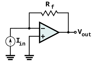
In electronics, a transimpedance amplifier (TIA) is a current to voltage converter, almost exclusively implemented with one or more operational amplifiers. The TIA can be used to amplify the current output of Geiger–Müller tubes, photo multiplier tubes, accelerometers, photo detectors and other types of sensors to a usable voltage. Current to voltage converters are used with sensors that have a current response that is more linear than the voltage response. This is the case with photodiodes where it is not uncommon for the current response to have better than 1% nonlinearity over a wide range of light input. The transimpedance amplifier presents a low impedance to the photodiode and isolates it from the output voltage of the operational amplifier. In its simplest form a transimpedance amplifier has just a large valued feedback resistor, Rf. The gain of the amplifier is set by this resistor and because the amplifier is in an inverting configuration, has a value of -Rf. There are several different configurations of transimpedance amplifiers, each suited to a particular application. The one factor they all have in common is the requirement to convert the low-level current of a sensor to a voltage. The gain, bandwidth, as well as current and voltage offsets change with different types of sensors, requiring different configurations of transimpedance amplifiers.

The current-feedback operational amplifier is a type of electronic amplifier whose inverting input is sensitive to current, rather than to voltage as in a conventional voltage-feedback operational amplifier (VFA). The CFA was invented by David Nelson at Comlinear Corporation, and first sold in 1982 as a hybrid amplifier, the CLC103. An early patent covering a CFA is U.S. Patent 4,502,020, David Nelson and Kenneth Saller. The integrated circuit CFAs were introduced in 1987 by both Comlinear and Elantec. They are usually produced with the same pin arrangements as VFAs, allowing the two types to be interchanged without rewiring when the circuit design allows. In simple configurations, such as linear amplifiers, a CFA can be used in place of a VFA with no circuit modifications, but in other cases, such as integrators, a different circuit design is required. The classic four-resistor differential amplifier configuration also works with a CFA, but the common-mode rejection ratio is poorer than that from a VFA.
