
An operational amplifier is a DC-coupled electronic voltage amplifier with a differential input, a (usually) single-ended output, and an extremely high gain. Its name comes from its original use of performing mathematical operations in analog computers.

A negative-feedback amplifier is an electronic amplifier that subtracts a fraction of its output from its input, so that negative feedback opposes the original signal. The applied negative feedback can improve its performance and reduces sensitivity to parameter variations due to manufacturing or environment. Because of these advantages, many amplifiers and control systems use negative feedback.

In electronics, a common-base amplifier is one of three basic single-stage bipolar junction transistor (BJT) amplifier topologies, typically used as a current buffer or voltage amplifier.

In electronics, a Schmitt trigger is a comparator circuit with hysteresis implemented by applying positive feedback to the noninverting input of a comparator or differential amplifier. It is an active circuit which converts an analog input signal to a digital output signal. The circuit is named a trigger because the output retains its value until the input changes sufficiently to trigger a change. In the non-inverting configuration, when the input is higher than a chosen threshold, the output is high. When the input is below a different (lower) chosen threshold the output is low, and when the input is between the two levels the output retains its value. This dual threshold action is called hysteresis and implies that the Schmitt trigger possesses memory and can act as a bistable multivibrator. There is a close relation between the two kinds of circuits: a Schmitt trigger can be converted into a latch and a latch can be converted into a Schmitt trigger.

In electronics, a common-emitter amplifier is one of three basic single-stage bipolar-junction-transistor (BJT) amplifier topologies, typically used as a voltage amplifier. It offers high current gain, medium input resistance and a high output resistance. The output of a common emitter amplifier is inverted; i.e. for a sine wave input signal, the output signal is 180 degrees out of phase with respect to the input.
A current mirror is a circuit designed to copy a current through one active device by controlling the current in another active device of a circuit, keeping the output current constant regardless of loading. The current being "copied" can be, and sometimes is, a varying signal current. Conceptually, an ideal current mirror is simply an ideal inverting current amplifier that reverses the current direction as well, or it could consist of a current-controlled current source (CCCS). The current mirror is used to provide bias currents and active loads to circuits. It can also be used to model a more realistic current source.
A Colpitts oscillator, invented in 1918 by Canadian-American engineer Edwin H. Colpitts using vacuum tubes, is one of a number of designs for LC oscillators, electronic oscillators that use a combination of inductors (L) and capacitors (C) to produce an oscillation at a certain frequency. The distinguishing feature of the Colpitts oscillator is that the feedback for the active device is taken from a voltage divider made of two capacitors in series across the inductor.

The asymptotic gain model is a representation of the gain of negative feedback amplifiers given by the asymptotic gain relation:
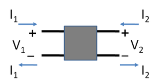
In electronics, a two-port network is an electrical network or device with two pairs of terminals to connect to external circuits. Two terminals constitute a port if the currents applied to them satisfy the essential requirement known as the port condition: the current entering one terminal must equal the current emerging from the other terminal on the same port. The ports constitute interfaces where the network connects to other networks, the points where signals are applied or outputs are taken. In a two-port network, often port 1 is considered the input port and port 2 is considered the output port.

In electronics, a common-source amplifier is one of three basic single-stage field-effect transistor (FET) amplifier topologies, typically used as a voltage or transconductance amplifier. The easiest way to tell if a FET is common source, common drain, or common gate is to examine where the signal enters and leaves. The remaining terminal is what is known as "common". In this example, the signal enters the gate, and exits the drain. The only terminal remaining is the source. This is a common-source FET circuit. The analogous bipolar junction transistor circuit may be viewed as a transconductance amplifier or as a voltage amplifier.. As a transconductance amplifier, the input voltage is seen as modulating the current going to the load. As a voltage amplifier, input voltage modulates the current flowing through the FET, changing the voltage across the output resistance according to Ohm's law. However, the FET device's output resistance typically is not high enough for a reasonable transconductance amplifier, nor low enough for a decent voltage amplifier. As seen below in the formula, the voltage gain depends on the load resistance, so it cannot be applied to drive low-resistance devices, such as a speaker. Another major drawback is the amplifier's limited high-frequency response. Therefore, in practice the output often is routed through either a voltage follower, or a current follower, to obtain more favorable output and frequency characteristics. The CS–CG combination is called a cascode amplifier.
The cascode is a two-stage amplifier that consists of a common emitter stage feeding into a common base stage when using bipolar junction transistors (BJTs) or alternatively a common source stage feeding a common gate stage when using field-effect transistors (FETs).
This article illustrates some typical operational amplifier applications. A non-ideal operational amplifier's equivalent circuit has a finite input impedance, a non-zero output impedance, and a finite gain. A real op-amp has a number of non-ideal features as shown in the diagram, but here a simplified schematic notation is used, many details such as device selection and power supply connections are not shown. Operational amplifiers are optimised for use with negative feedback, and this article discusses only negative-feedback applications. When positive feedback is required, a comparator is usually more appropriate. See Comparator applications for further information.

Channel length modulation (CLM) is an effect in field effect transistors, a shortening of the length of the inverted channel region with increase in drain bias for large drain biases. The result of CLM is an increase in current with drain bias and a reduction of output resistance. It is one of several short-channel effects in MOSFET scaling. It also causes distortion in JFET amplifiers.
A Wilson current mirror is a three-terminal circuit that accepts an input current at the input terminal and provides a "mirrored" current source or sink output at the output terminal. The mirrored current is a precise copy of the input current. It may be used as a Wilson current source by applying a constant bias current to the input branch as in Fig. 2. The circuit is named after George R. Wilson, an integrated circuit design engineer who worked for Tektronix. Wilson devised this configuration in 1967 when he and Barrie Gilbert challenged each other to find an improved current mirror overnight that would use only three transistors. Wilson won the challenge.

The operational transconductance amplifier (OTA) is an amplifier that outputs a current proportional to its input voltage. Thus, it is a voltage controlled current source (VCCS). Three types of OTAs are single-input single-output, differential-input single-output, and differential-input differential-output, however this article focuses on differential-input single-output. There may be an additional input for a current to control the amplifier's transconductance.

Bipolar transistors must be properly biased to operate correctly. In circuits made with individual devices, biasing networks consisting of resistors are commonly employed. Much more elaborate biasing arrangements are used in integrated circuits, for example, bandgap voltage references and current mirrors. The voltage divider configuration achieves the correct voltages by the use of resistors in certain patterns. By selecting the proper resistor values, stable current levels can be achieved that vary only little over temperature and with transistor properties such as β.
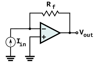
In electronics, a transimpedance amplifier (TIA) is a current to voltage converter, almost exclusively implemented with one or more operational amplifiers. The TIA can be used to amplify the current output of Geiger–Müller tubes, photo multiplier tubes, accelerometers, photo detectors and other types of sensors to a usable voltage. Current to voltage converters are used with sensors that have a current response that is more linear than the voltage response. This is the case with photodiodes where it is not uncommon for the current response to have better than 1% nonlinearity over a wide range of light input. The transimpedance amplifier presents a low impedance to the photodiode and isolates it from the output voltage of the operational amplifier. In its simplest form a transimpedance amplifier has just a large valued feedback resistor, Rf. The gain of the amplifier is set by this resistor and because the amplifier is in an inverting configuration, has a value of -Rf. There are several different configurations of transimpedance amplifiers, each suited to a particular application. The one factor they all have in common is the requirement to convert the low-level current of a sensor to a voltage. The gain, bandwidth, as well as current and voltage offsets change with different types of sensors, requiring different configurations of transimpedance amplifiers.

A FET amplifier is an amplifier that uses one or more field-effect transistors (FETs). The most common type of FET amplifier is the MOSFET amplifier, which uses metal–oxide–semiconductor FETs (MOSFETs). The main advantage of a FET used for amplification is that it has very high input impedance and low output impedance.

In the theory of electrical networks, a dependent source is a voltage source or a current source whose value depends on a voltage or current elsewhere in the network.

A double-tuned amplifier is a tuned amplifier with transformer coupling between the amplifier stages in which the inductances of both the primary and secondary windings are tuned separately with a capacitor across each. The scheme results in a wider bandwidth and steeper skirts than a single tuned circuit would achieve.


