Related Research Articles
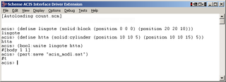
The 3D ACIS Modeler (ACIS) is a geometric modeling kernel developed by Spatial Corporation, part of Dassault Systemes. ACIS is used by many software developers in industries such as computer-aided design (CAD), computer-aided manufacturing (CAM), computer-aided engineering (CAE), architecture, engineering and construction (AEC), coordinate-measuring machine (CMM), 3D animation, and shipbuilding. ACIS provides software developers and manufacturers the underlying 3D modeling functionality.

In 3D computer graphics and solid modeling, a polygon mesh is a collection of vertices, edges and faces that defines the shape of a polyhedral object. The faces usually consist of triangles, quadrilaterals (quads), or other simple convex polygons (n-gons), since this simplifies rendering, but may also be more generally composed of concave polygons, or even polygons with holes.
Netpbm is an open-source package of graphics programs and a programming library. It is used mainly in the Unix world, where one can find it included in all major open-source operating system distributions, but also works on Microsoft Windows, macOS, and other operating systems.
OBJ is a geometry definition file format first developed by Wavefront Technologies for its Advanced Visualizer animation package. The file format is open and has been adopted by other 3D graphics application vendors.
In 3D computer graphics, polygonal modeling is an approach for modeling objects by representing or approximating their surfaces using polygon meshes. Polygonal modeling is well suited to scanline rendering and is therefore the method of choice for real-time computer graphics. Alternate methods of representing 3D objects include NURBS surfaces, subdivision surfaces, and equation-based representations used in ray tracers.
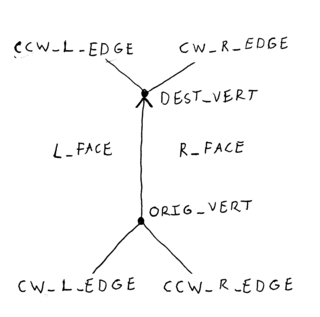
In computer graphics, the winged edge data structure is a way to represent polygon meshes in computer memory. It is a type of boundary representation and describes both the geometry and topology of a model. Three types of records are used: vertex records, edge records, and face records. Given a reference to an edge record, one can answer several types of adjacency queries in constant time. This kind of adjacency information is useful for algorithms such as subdivision surface.

STL is a file format native to the stereolithography CAD software created by 3D Systems. Chuck Hull, the inventor of stereolithography and 3D Systems’ founder, reports that the file extension is an abbreviation for stereolithography.
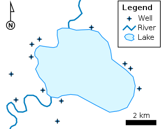
The shapefile format is a geospatial vector data format for geographic information system (GIS) software. It is developed and regulated by Esri as a mostly open specification for data interoperability among Esri and other GIS software products. The shapefile format can spatially describe vector features: points, lines, and polygons, representing, for example, water wells, rivers, and lakes. Each item usually has attributes that describe it, such as name or temperature.
3DXML is a proprietary 3D file format developed by Dassault Systemes under its 3DVIA Brand. It uses an XML container whose specifications were published. It should not be confused with X3D, the ISO standard XML-based file format for representing 3D computer graphics.
MeshLab is a 3D mesh processing software system that is oriented to the management and processing of unstructured large meshes and provides a set of tools for editing, cleaning, healing, inspecting, rendering, and converting these kinds of meshes. MeshLab is free and open-source software, subject to the requirements of the GNU General Public License (GPL), version 2 or later, and is used as both a complete package and a library powering other software. It is well known in the more technical fields of 3D development and data handling.
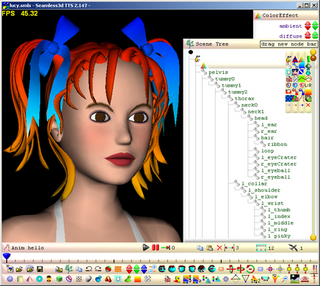
Seamless3d is an open-source 3D modeling software available under the MIT license.
3DS is one of the file formats used by the Autodesk 3ds Max 3D modeling, animation and rendering software.
OpenCTM is a 3D geometry technology for storing triangle-based meshes in a compact format.
The Point Cloud Library (PCL) is an open-source library of algorithms for point cloud processing tasks and 3D geometry processing, such as occur in three-dimensional computer vision. The library contains algorithms for filtering, feature estimation, surface reconstruction, 3D registration, model fitting, object recognition, and segmentation. Each module is implemented as a smaller library that can be compiled separately. PCL has its own data format for storing point clouds - PCD, but also allows datasets to be loaded and saved in many other formats. It is written in C++ and released under the BSD license.
Additive manufacturing file format (AMF) is an open standard for describing objects for additive manufacturing processes such as 3D printing. The official ISO/ASTM 52915:2016 standard is an XML-based format designed to allow any computer-aided design software to describe the shape and composition of any 3D object to be fabricated on any 3D printer via a computer-aided manufacturing software. Unlike its predecessor STL format, AMF has native support for color, materials, lattices, and constellations.
OFF is a geometry definition file format containing the description of the composing polygons of a geometric object. It can store 2D or 3D objects, and simple extensions allow it to represent higher-dimensional objects as well. Though originally developed for Geomview, a geometry visualization software, other software has adapted the simple standard.
The Esri TIN format is a popular yet proprietary geospatial vector data format for geographic information system (GIS) software for storing elevation data as a triangulated irregular network. It is developed and regulated by Esri, US. The Esri TIN format can spatially describe elevation information including breaking edge features. Each points and triangle can carry a tag information. A TIN stored in this file format can have any shape, cover multiple regions and contain holes.
This is a glossary of terms relating to computer graphics.
glTF is a standard file format for three-dimensional scenes and models. A glTF file uses one of two possible file extensions: .gltf (JSON/ASCII) or .glb (binary). Both .gltf and .glb files may reference external binary and texture resources. Alternatively, both formats may be self-contained by directly embedding binary data buffers. An open standard developed and maintained by the Khronos Group, it supports 3D model geometry, appearance, scene graph hierarchy, and animation. It is intended to be a streamlined, interoperable format for the delivery of 3D assets, while minimizing file size and runtime processing by apps. As such, its creators have described it as the "JPEG of 3D."
JMesh is a JSON-based portable and extensible file format for the storage and interchange of unstructured geometric data, including discretized geometries such as triangular and tetrahedral meshes, parametric geometries such as NURBS curves and surfaces, and constructive geometries such as constructive solid geometry (CGS) of shape primitives and meshes. Built upon the JData specification, a JMesh file utilizes the JSON and Universal Binary JSON (UBJSON) constructs to serialize and encode geometric data structures, therefore, it can be directly processed by most existing JSON and UBJSON parsers. The JMesh specification defines a list of JSON-compatible constructs to encode geometric data, including N-dimensional (ND) vertices, curves, surfaces, solid elements, shape primitives, their interactions and spatial relations, together with their associated properties, such as numerical values, colors, normals, materials, textures and other properties related to graphics data manipulation, 3-D fabrication, computer graphics rendering and animations.
References
- ↑ Greg Turk. "The PLY Polygon File Format". Archived from the original on 2016-12-04.
- ↑ Greg Turk. "The PLY Polygon File Format (extended)" (PDF).