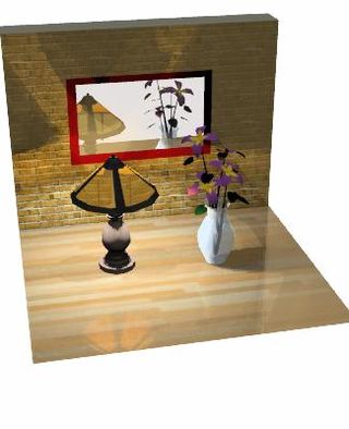
An image rendered using path tracing, demonstrating notable features of the technique
Path tracing is a computer graphicsMonte Carlo method of rendering images of three-dimensional scenes such that the global illumination is faithful to reality. Fundamentally, the algorithm is integrating over all the illuminance arriving to a single point on the surface of an object. This illuminance is then reduced by a surface reflectance function (BRDF) to determine how much of it will go towards the viewpoint camera. This integration procedure is repeated for every pixel in the output image. When combined with physically accurate models of surfaces, accurate models of real light sources, and optically correct cameras, path tracing can produce still images that are indistinguishable from photographs.
Due to its accuracy, unbiased nature, and algorithmic simplicity, path tracing is used to generate reference images when testing the quality of other rendering algorithms. However, the path tracing algorithm is relatively inefficient: A very large number of rays must be traced to get high-quality images free of noise artifacts. Several variants have been introduced which are more efficient than the original algorithm for many scenes, including bidirectional path tracing, volumetric path tracing, and Metropolis light transport.
The rendering equation and its use in computer graphics was presented by James Kajiya in 1986. Path tracing was introduced then as an algorithm to find a numerical solution to the integral of the rendering equation. A decade later, Lafortune suggested many refinements, including bidirectional path tracing.
Metropolis light transport, a method of perturbing previously found paths in order to increase performance for difficult scenes, was introduced in 1997 by Eric Veach and Leonidas J. Guibas.
More recently, CPUs and GPUs have become powerful enough to render images more quickly, causing more widespread interest in path tracing algorithms. Tim Purcell first presented a global illumination algorithm running on a GPU in 2002. In February 2009, Austin Robison of Nvidia demonstrated the first commercial implementation of a path tracer running on a GPU , and other implementations have followed, such as that of Vladimir Koylazov in August 2009. This was aided by the maturing of GPGPU programming toolkits such as CUDA and OpenCL and GPU ray tracing SDKs such as OptiX.
Path tracing has played an important role in the film industry. Earlier films had relied on scanline rendering to produce CG visual effects and animation. In 1998, Blue Sky Studios rendered the Academy Award-winning short film Bunny with their proprietary CGI Studio path tracing renderer, featuring soft shadows and indirect illumination effects. Sony Pictures Imageworks' Monster House was, in 2006, the first animated feature film to be rendered entirely in a path tracer, using the commercial Arnold renderer. Also, Walt Disney Animation Studios has been using its own optimized path tracer known as Hyperion ever since the production of Big Hero 6 in 2014.Pixar Animation Studios has also adopted path tracing for its commercial RenderMan renderer.
Description
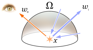
Kajiya's rendering equation adheres to three particular principles of optics; the Principle of Global Illumination, the Principle of Equivalence (reflected light is equivalent to emitted light), and the Principle of Direction (reflected light and scattered light have a direction).
In the real world, objects and surfaces are visible due to the fact that they are reflecting light. This reflected light then illuminates other objects in turn. From that simple observation, two principles follow.
I. For a given indoor scene, every object in the room must contribute illumination to every other object.
II. Second, there is no distinction to be made between illumination emitted from a light source and illumination reflected from a surface.
Invented in 1984, a rather different method called radiosity was faithful to both principles. However, radiosity relates the total illuminance falling on a surface with a uniform luminance that leaves the surface. This forced all surfaces to be Lambertian, or "perfectly diffuse". While radiosity received a lot of attention at its introduction, perfectly diffuse surfaces do not exist in the real world. The realization that scattering from a surface depends on both incoming and outgoing directions is the key principle behind the bidirectional reflectance distribution function (BRDF). This direction dependence was a focus of research resulting in the publication of important ideas throughout the 1990s, since accounting for direction always exacted a price of steep increases in calculation times on desktop computers. Principle III follows.
III. The illumination coming from surfaces must scatter in a particular direction that is some function of the incoming direction of the arriving illumination, and the outgoing direction being sampled.
Kajiya's equation is a complete summary of these three principles, and path tracing, which approximates a solution to the equation, remains faithful to them in its implementation. There are other principles of optics which are not the focus of Kajiya's equation, and therefore are often difficult or incorrectly simulated by the algorithm. Path tracing is confounded by optical phenomena not contained in the three principles. For example,
Bright, sharp caustics; radiance scales by the density of illuminance in space.
The following pseudocode is a procedure for performing naive path tracing. The TracePath function calculates a single sample of a pixel, where only the Gathering Path is considered.
ColorTracePath(Rayray,countdepth){if(depth>=MaxDepth){returnBlack;// Bounced enough times.}ray.FindNearestObject();if(ray.hitSomething==false){returnBlack;// Nothing was hit.}Materialmaterial=ray.thingHit->material;Coloremittance=material.emittance;// Pick a random direction from here and keep going.RaynewRay;newRay.origin=ray.pointWhereObjWasHit;// This is NOT a cosine-weighted distribution!newRay.direction=RandomUnitVectorInHemisphereOf(ray.normalWhereObjWasHit);// Probability of the newRayconstfloatp=1/(2*PI);// Compute the BRDF for this ray (assuming Lambertian reflection)floatcos_theta=DotProduct(newRay.direction,ray.normalWhereObjWasHit);ColorBRDF=material.reflectance/PI;// Recursively trace reflected light sources.Colorincoming=TracePath(newRay,depth+1);// Apply the Rendering Equation here.returnemittance+(BRDF*incoming*cos_theta/p);}voidRender(ImagefinalImage,countnumSamples){foreach(pixelinfinalImage){foreach(iinnumSamples){Rayr=camera.generateRay(pixel);pixel.color+=TracePath(r,0);}pixel.color/=numSamples;// Average samples.}}
All the samples are then averaged to obtain the output color. Note this method of always sampling a random ray in the normal's hemisphere only works well for perfectly diffuse surfaces. For other materials, one generally has to use importance sampling, i.e. probabilistically select a new ray according to the BRDF's distribution. For instance, a perfectly specular (mirror) material would not work with the method above, as the probability of the new ray being the correct reflected ray – which is the only ray through which any radiance will be reflected – is zero. In these situations, one must divide the reflectance by the probability density function of the sampling scheme, as per Monte Carlo integration (in the naive case above, there is no particular sampling scheme, so the PDF turns out to be ).
There are other considerations to take into account to ensure conservation of energy. In particular, in the naive case, the reflectance of a diffuse BRDF must not exceed or the object will reflect more light than it receives (this however depends on the sampling scheme used, and can be difficult to get right).
Bidirectional path tracing
Sampling the integral can be done by either of the following two distinct approaches:
Backwards path tracing, where paths are generated starting from the camera and bouncing around the scene until they encounter a light source. This is referred to as "backwards" because starting paths from the camera and moving towards the light source is opposite the direction that the light is actually traveling. It still produces the same result because all optical systems are reversible.
Light tracing (or forwards path tracing), where paths are generated starting from the light sources and bouncing around the scene until they encounter the camera.
In both cases, a technique called next event estimation can be used to reduce variance. This works by directly sampling an important feature (the camera in the case of light tracing, or a light source in the case of backwards path tracing) instead of waiting for a path to hit it by chance. This technique is usually effective, but becomes less useful when specular or near-specular BRDFs are present. For backwards path tracing, this creates high variance for caustic paths that interact with a diffuse surface, then bounce off a specular surface before hitting a light source. Next event estimation cannot be used to sample these paths directly from the diffuse surface, because the specular interaction is in the middle. Likewise, it cannot be used to sample paths from the specular surface because there is only one direction that the light can bounce. Light tracing has a similar issue when paths interact with a specular surface before hitting the camera. Because this situation is significantly more common, and noisy (or completely black) glass objects are very visually disruptive, backwards path tracing is the only method that is used for unidirectional path tracing in practice.
Bidirectional path tracing provides an algorithm that combines the two approaches and can produce lower variance than either method alone. For each sample, two paths are traced independently: one using from the light source and one from the camera. This produces a set of possible sampling strategies, where every vertex of one path can be connected directly to every vertex of the other. The original light tracing and backwards path tracing algorithms are both special cases of these strategies. For light tracing, it is connecting the vertices of the camera path directly to the first vertex of the light path. For backwards path tracing, it is connecting the vertices of the light path to the first vertex of the camera path. In addition, there are several completely new sampling strategies, where intermediate vertices are connected. Weighting all of these sampling strategies using multiple importance sampling creates a new sampler that can converge faster than unidirectional path tracing, even though more work is required for each sample. This works particularly well for caustics or scenes that are lit primarily through indirect lighting.
Performance
Noise decreases as the number of samples per pixel increase. The top left shows 1 sample per pixel, and doubles from left to right each square.
A path tracer continuously samples pixels of an image. The image starts to become recognizable after only a few samples per pixel, perhaps 100. However, for the image to "converge" and reduce noise to acceptable levels usually takes around 5000 samples for most images, and many more for pathological cases. Noise is particularly a problem for animations, giving them a normally unwanted "film grain" quality of random speckling.
The central performance bottleneck in path tracing is the complex geometrical calculation of casting a ray. Importance sampling is a technique which is motivated to cast fewer rays through the scene while still converging correctly to outgoing luminance on the surface point. This is done by casting more rays in directions in which the luminance would have been greater anyway. If the density of rays cast in certain directions matches the strength of contributions in those directions, the result is identical, but far fewer rays were actually cast. Importance sampling is used to match ray density to Lambert's cosine law, and also used to match BRDFs.
Metropolis light transport can result in a lower-noise image with fewer samples. This algorithm was created in order to get faster convergence in scenes in which the light must pass through odd corridors or small holes in order to reach the part of the scene that the camera is viewing. It has also shown promise in correctly rendering pathological situations with caustics. Instead of generating random paths, new sampling paths are created as slight mutations of existing ones. In this sense, the algorithm "remembers" the successful paths from light sources to the camera.
Scattering distribution functions
Scattering distribution functions
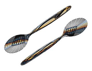
The reflective properties (amount, direction, and color) of surfaces are modeled using BRDFs. The equivalent for transmitted light (light that goes through the object) are BSDFs. A path tracer can take full advantage of complex, carefully modeled or measured distribution functions, which controls the appearance ("material", "texture", or "shading" in computer graphics terms) of an object.
^Kajiya, J. T. (1986). "The rendering equation". Proceedings of the 13th annual conference on Computer graphics and interactive techniques. ACM. CiteSeerX10.1.1.63.1402.
^Purcell, T J; Buck, I; Mark, W; and Hanrahan, P, "Ray Tracing on Programmable Graphics Hardware", Proc. SIGGRAPH 2002, 703 – 712. See also Purcell, T, Ray tracing on a stream processor (PhD thesis), 2004.
SmallPt is an educational path tracer by Kevin Beason. It uses 99 lines of C++ (including scene description). This page has a good set of examples of noise resulting from this technique.
Related Research Articles
Rendering or image synthesis is the process of generating a photorealistic or non-photorealistic image from a 2D or 3D model by means of a computer program. The resulting image is referred to as the render. Multiple models can be defined in a scene file containing objects in a strictly defined language or data structure. The scene file contains geometry, viewpoint, texture, lighting, and shading information describing the virtual scene. The data contained in the scene file is then passed to a rendering program to be processed and output to a digital image or raster graphics image file. The term "rendering" is analogous to the concept of an artist's impression of a scene. The term "rendering" is also used to describe the process of calculating effects in a video editing program to produce the final video output.
Global illumination (GI), or indirect illumination, is a group of algorithms used in 3D computer graphics that are meant to add more realistic lighting to 3D scenes. Such algorithms take into account not only the light that comes directly from a light source, but also subsequent cases in which light rays from the same source are reflected by other surfaces in the scene, whether reflective or not.
In 3D computer graphics, radiosity is an application of the finite element method to solving the rendering equation for scenes with surfaces that reflect light diffusely. Unlike rendering methods that use Monte Carlo algorithms, which handle all types of light paths, typical radiosity only account for paths which leave a light source and are reflected diffusely some number of times before hitting the eye. Radiosity is a global illumination algorithm in the sense that the illumination arriving on a surface comes not just directly from the light sources, but also from other surfaces reflecting light. Radiosity is viewpoint independent, which increases the calculations involved, but makes them useful for all viewpoints.
In 3-D computer graphics, ray tracing is a technique for modeling light transport for use in a wide variety of rendering algorithms for generating digital images.
The Persistence of Vision Ray Tracer, most commonly acronymed as POV-Ray, is a cross-platform ray-tracing program that generates images from a text-based scene description. It was originally based on DKBTrace, written by David Kirk Buck and Aaron A. Collins for Amiga computers. There are also influences from the earlier Polyray raytracer because of contributions from its author, Alexander Enzmann. POV-Ray is free and open-source software, with the source code available under the AGPL-3.0-or-later license.
Metropolis light transport (MLT) is a global illumination application of a variant of the Monte Carlo method called the Metropolis–Hastings algorithm to the rendering equation for generating images from detailed physical descriptions of three-dimensional scenes.
In computer graphics, photon mapping is a two-pass global illumination rendering algorithm developed by Henrik Wann Jensen between 1995 and 2001 that approximately solves the rendering equation for integrating light radiance at a given point in space. Rays from the light source and rays from the camera are traced independently until some termination criterion is met, then they are connected in a second step to produce a radiance value. The algorithm is used to realistically simulate the interaction of light with different types of objects. Specifically, it is capable of simulating the refraction of light through a transparent substance such as glass or water, diffuse interreflection between illuminated objects, the subsurface scattering of light in translucent materials, and some of the effects caused by particulate matter such as smoke or water vapor. Photon mapping can also be extended to more accurate simulations of light, such as spectral rendering. Progressive photon mapping (PPM) starts with ray tracing and then adds more and more photon mapping passes to provide a progressively more accurate render.
Shading refers to the depiction of depth perception in 3D models or illustrations by varying the level of darkness. Shading tries to approximate local behavior of light on the object's surface and is not to be confused with techniques of adding shadows, such as shadow mapping or shadow volumes, which fall under global behavior of light.
Ray casting is the methodological basis for 3D CAD/CAM solid modeling and image rendering. It is essentially the same as ray tracing for computer graphics where virtual light rays are "cast" or "traced" on their path from the focal point of a camera through each pixel in the camera sensor to determine what is visible along the ray in the 3D scene. The term "Ray Casting" was introduced by Scott Roth while at the General Motors Research Labs from 1978–1980. His paper, "Ray Casting for Modeling Solids", describes modeled solid objects by combining primitive solids, such as blocks and cylinders, using the set operators union (+), intersection (&), and difference (-). The general idea of using these binary operators for solid modeling is largely due to Voelcker and Requicha's geometric modelling group at the University of Rochester. See solid modeling for a broad overview of solid modeling methods. This figure on the right shows a U-Joint modeled from cylinders and blocks in a binary tree using Roth's ray casting system in 1979.
In computer graphics, the rendering equation is an integral equation in which the equilibrium radiance leaving a point is given as the sum of emitted plus reflected radiance under a geometric optics approximation. It was simultaneously introduced into computer graphics by David Immel et al. and James Kajiya in 1986. The various realistic rendering techniques in computer graphics attempt to solve this equation.
Beam tracing is an algorithm to simulate wave propagation. It was developed in the context of computer graphics to render 3D scenes, but it has been also used in other similar areas such as acoustics and electromagnetism simulations.
The bidirectional reflectance distribution function (BRDF), symbol , is a function of four real variables that defines how light from a source is reflected off an opaque surface. It is employed in the optics of real-world light, in computer graphics algorithms, and in computer vision algorithms. The function takes an incoming light direction, , and outgoing direction, , and returns the ratio of reflected radiance exiting along to the irradiance incident on the surface from direction . Each direction is itself parameterized by azimuth angle and zenith angle , therefore the BRDF as a whole is a function of 4 variables. The BRDF has units sr−1, with steradians (sr) being a unit of solid angle.
In computer graphics, environment mapping, or reflection mapping, is an efficient image-based lighting technique for approximating the appearance of a reflective surface by means of a precomputed texture. The texture is used to store the image of the distant environment surrounding the rendered object.
In computer graphics, per-pixel lighting refers to any technique for lighting an image or scene that calculates illumination for each pixel on a rendered image. This is in contrast to other popular methods of lighting such as vertex lighting, which calculates illumination at each vertex of a 3D model and then interpolates the resulting values over the model's faces to calculate the final per-pixel color values.
Volume ray casting, sometimes called volumetric ray casting, volumetric ray tracing, or volume ray marching, is an image-based volume rendering technique. It computes 2D images from 3D volumetric data sets. Volume ray casting, which processes volume data, must not be mistaken with ray casting in the sense used in ray tracing, which processes surface data. In the volumetric variant, the computation doesn't stop at the surface but "pushes through" the object, sampling the object along the ray. Unlike ray tracing, volume ray casting does not spawn secondary rays. When the context/application is clear, some authors simply call it ray casting. Because ray marching does not necessarily require an exact solution to ray intersection and collisions, it is suitable for real time computing for many applications for which ray tracing is unsuitable.
3D rendering is the 3D computer graphics process of converting 3D models into 2D images on a computer. 3D renders may include photorealistic effects or non-photorealistic styles.
Computer graphics lighting is the collection of techniques used to simulate light in computer graphics scenes. While lighting techniques offer flexibility in the level of detail and functionality available, they also operate at different levels of computational demand and complexity. Graphics artists can choose from a variety of light sources, models, shading techniques, and effects to suit the needs of each application.
Reflection in computer graphics is used to render reflective objects like mirrors and shiny surfaces.
Arnold is a computer program for rendering three-dimensional, computer-generated scenes using unbiased, physically-based, Monte Carlo path tracing techniques. Created in Spain by Marcos Fajardo and later co-developed by his company Solid Angle SL and Sony Pictures Imageworks, Arnold is one of the most widely used photorealistic rendering systems in computer graphics worldwide, particularly in animation and VFX for film and TV. Notable feature films that have used Arnold include Monster House, Cloudy with a Chance of Meatballs, Alice in Wonderland, Thor, Captain America, X-Men: First Class, The Avengers, Space Pirate Captain Harlock, Elysium, Pacific Rim, Gravity, Guardians of the Galaxy, Star Wars: The Force Awakens, Arrival and Blade Runner 2049. Notable television series include Game of Thrones, Westworld, Trollhunters, LOVE DEATH + ROBOTS, Jelly Jamm and The Mandalorian.
This is a glossary of terms relating to computer graphics.
This page is based on this Wikipedia article Text is available under the CC BY-SA 4.0 license; additional terms may apply. Images, videos and audio are available under their respective licenses.