Photoelasticity

Last updated
Plastic utensils in a photoelasticity experiment BiodegradablePlasticUtensils2.jpg
Plastic utensils in a photoelasticity experiment

In materials science, photoelasticity describes changes in the optical properties of a material under mechanical deformation. It is a property of all dielectric media and is often used to experimentally determine the stress distribution in a material.

Contents

History

The photoelastic phenomenon was first discovered by the Scottish physicist David Brewster, who immediately recognized it as stress-induced birefringence. [1] [2] That diagnosis was confirmed in a direct refraction experiment by Augustin-Jean Fresnel. [3] Experimental frameworks were developed at the beginning of the twentieth century with the works of E. G. Coker and L. N. G. Filon of University of London. Their book Treatise on Photoelasticity, published in 1930 by Cambridge Press, became a standard text on the subject. Between 1930 and 1940, many other books appeared on the subject, including books in Russian, German and French. Max M. Frocht published the classic two volume work, Photoelasticity, in the field. [4] At the same time, much development occurred in the field – great improvements were achieved in technique, and the equipment was simplified. With refinements in the technology, photoelastic experiments were extended to determining three-dimensional states of stress. In parallel to developments in experimental technique, the first phenomenological description of photoelasticity was given in 1890 by Friedrich Pockels, [5] however this was proved inadequate almost a century later by Nelson & Lax [6] as the description by Pockels only considered the effect of mechanical strain on the optical properties of the material.

With the advent of the digital polariscope – made possible by light-emitting diodes – continuous monitoring of structures under load became possible. This led to the development of dynamic photoelasticity, which has contributed greatly to the study of complex phenomena such as fracture of materials.

Applications

Photoelastic model to validate the stiffener model. Isochromatic fringe patterns around a steel platelet in a photo-elastic two-part epoxy resin. Photoelasticity stiffener.jpg
Photoelastic model to validate the stiffener model. Isochromatic fringe patterns around a steel platelet in a photo-elastic two-part epoxy resin.

Photoelasticity has been used for a variety of stress analyses and even for routine use in design, particularly before the advent of numerical methods, such as finite elements or boundary elements. [7] Digitization of polariscopy enables fast image acquisition and data processing, which allows its industrial applications to control quality of manufacturing process for materials such as glass [8] and polymer. [9] Dentistry utilizes photoelasticity to analyze strain in denture materials. [10]

Photoelasticity can successfully be used to investigate the highly localized stress state within masonry [11] [12] [13] or in proximity of a rigid line inclusion (stiffener) embedded in an elastic medium. [14] In the former case, the problem is nonlinear due to the contacts between bricks, while in the latter case the elastic solution is singular, so that numerical methods may fail to provide correct results. These can be obtained through photoelastic techniques. Dynamic photoelasticity integrated with high-speed photography is utilized to investigate fracture behavior in materials. [15] Another important application of the photoelasticity experiments is to study the stress field around bi-material notches. [16] Bi-material notches exist in many engineering application like welded or adhesively bonded structures.

Formal definition

For a linear dielectric material the change in the inverse permittivity tensor with respect to the deformation (the gradient of the displacement ) is described by [17]

where is the fourth-rank photoelasticity tensor, is the linear displacement from equilibrium, and denotes differentiation with respect to the Cartesian coordinate . For isotropic materials, this definition simplifies to [18]

where is the symmetric part of the photoelastic tensor (the photoelastic strain tensor), and is the linear strain. The antisymmetric part of is known as the roto-optic tensor. From either definition, it is clear that deformations to the body may induce optical anisotropy, which can cause an otherwise optically isotropic material to exhibit birefringence. Although the symmetric photoelastic tensor is most commonly defined with respect to mechanical strain, it is also possible to express photoelasticity in terms of the mechanical stress.

Experimental principles

Tension lines in a plastic protractor seen under cross-polarized light Plastic Protractor Polarized 05375.jpg
Tension lines in a plastic protractor seen under cross-polarized light

The experimental procedure relies on the property of birefringence, as exhibited by certain transparent materials. Birefringence is a phenomenon in which a ray of light passing through a given material experiences two refractive indices. The property of birefringence (or double refraction) is observed in many optical crystals. Upon the application of stresses, photoelastic materials exhibit the property of birefringence, and the magnitude of the refractive indices at each point in the material is directly related to the state of stresses at that point. Information such as maximum shear stress and its orientation are available by analyzing the birefringence with an instrument called a polariscope.

When a ray of light passes through a photoelastic material, its electromagnetic wave components are resolved along the two principal stress directions and each component experiences a different refractive index due to the birefringence. The difference in the refractive indices leads to a relative phase retardation between the two components. Assuming a thin specimen made of isotropic materials, where two-dimensional photoelasticity is applicable, the magnitude of the relative retardation is given by the stress-optic law: [19]

where Δ is the induced retardation, C is the stress-optic coefficient, t is the specimen thickness, λ is the vacuum wavelength, and σ1 and σ2 are the first and second principal stresses, respectively. The retardation changes the polarization of transmitted light. The polariscope combines the different polarization states of light waves before and after passing the specimen. Due to optical interference of the two waves, a fringe pattern is revealed. The number of fringe order N is denoted as

which depends on relative retardation. By studying the fringe pattern one can determine the state of stress at various points in the material.

For materials that do not show photoelastic behavior, it is still possible to study the stress distribution. The first step is to build a model, using photoelastic materials, which has geometry similar to the real structure under investigation. The loading is then applied in the same way to ensure that the stress distribution in the model is similar to the stress in the real structure.

Isoclinics and isochromatics

Isoclinics are the loci of the points in the specimen along which the principal stresses are in the same direction.[ citation needed ]

Isochromatics are the loci of the points along which the difference in the first and second principal stress remains the same. Thus they are the lines which join the points with equal maximum shear stress magnitude. [20]

Two-dimensional photoelasticity

Photoelastic experiment showing the internal stress distribution inside the cover of a Jewel case Photoelasticimetry1.JPG
Photoelastic experiment showing the internal stress distribution inside the cover of a Jewel case

Photoelasticity can describe both three-dimensional and two-dimensional states of stress. However, examining photoelasticity in three-dimensional systems is more involved than two-dimensional or plane-stress system. So the present section deals with photoelasticity in a plane stress system. This condition is achieved when the thickness of the prototype is much smaller as compared to dimensions in the plane.[ citation needed ] Thus one is only concerned with stresses acting parallel to the plane of the model, as other stress components are zero. The experimental setup varies from experiment to experiment. The two basic kinds of setup used are plane polariscope and circular polariscope.[ citation needed ]

The working principle of a two-dimensional experiment allows the measurement of retardation, which can be converted to the difference between the first and second principal stress and their orientation. To further get values of each stress component, a technique called stress-separation is required. [21] Several theoretical and experimental methods are utilized to provide additional information to solve individual stress components.

Plane polariscope setup

The setup consists of two linear polarizers and a light source. The light source can either emit monochromatic light or white light depending upon the experiment. First the light is passed through the first polarizer which converts the light into plane polarized light. The apparatus is set up in such a way that this plane polarized light then passes through the stressed specimen. This light then follows, at each point of the specimen, the direction of principal stress at that point. The light is then made to pass through the analyzer and we finally get the fringe pattern.[ citation needed ]

The fringe pattern in a plane polariscope setup consists of both the isochromatics and the isoclinics. The isoclinics change with the orientation of the polariscope while there is no change in the isochromatics.[ citation needed ]

Transmission Circular Polariscope
The same device functions as a plane polariscope when quarter wave plates are taken aside or rotated so their axes parallel to polarization axes Transmission Circular Polariscope.svg
Transmission Circular Polariscope
The same device functions as a plane polariscope when quarter wave plates are taken aside or rotated so their axes parallel to polarization axes

Circular polariscope setup

In a circular polariscope setup two quarter-wave plates are added to the experimental setup of the plane polariscope. The first quarter-wave plate is placed in between the polarizer and the specimen and the second quarter-wave plate is placed between the specimen and the analyzer. The effect of adding the quarter-wave plate after the source-side polarizer is that we get circularly polarized light passing through the sample. The analyzer-side quarter-wave plate converts the circular polarization state back to linear before the light passes through the analyzer.[ citation needed ]

The basic advantage of a circular polariscope over a plane polariscope is that in a circular polariscope setup we only get the isochromatics and not the isoclinics. This eliminates the problem of differentiating between the isoclinics and the isochromatics.[ citation needed ]

See also

Related Research Articles

<span class="mw-page-title-main">Fresnel equations</span> Equations of light transmission and reflection

The Fresnel equations describe the reflection and transmission of light when incident on an interface between different optical media. They were deduced by French engineer and physicist Augustin-Jean Fresnel who was the first to understand that light is a transverse wave, when no one realized that the waves were electric and magnetic fields. For the first time, polarization could be understood quantitatively, as Fresnel's equations correctly predicted the differing behaviour of waves of the s and p polarizations incident upon a material interface.

In optics, polarized light can be described using the Jones calculus, invented by R. C. Jones in 1941. Polarized light is represented by a Jones vector, and linear optical elements are represented by Jones matrices. When light crosses an optical element the resulting polarization of the emerging light is found by taking the product of the Jones matrix of the optical element and the Jones vector of the incident light. Note that Jones calculus is only applicable to light that is already fully polarized. Light which is randomly polarized, partially polarized, or incoherent must be treated using Mueller calculus.

<span class="mw-page-title-main">Refractive index</span> Ratio of the speed of light in vacuum to that in the medium

In optics, the refractive index of an optical medium is a dimensionless number that gives the indication of the light bending ability of that medium.

<span class="mw-page-title-main">Optical rotation</span> Rotation of the plane of linearly polarized light as it travels through a chiral material

Optical rotation, also known as polarization rotation or circular birefringence, is the rotation of the orientation of the plane of polarization about the optical axis of linearly polarized light as it travels through certain materials. Circular birefringence and circular dichroism are the manifestations of optical activity. Optical activity occurs only in chiral materials, those lacking microscopic mirror symmetry. Unlike other sources of birefringence which alter a beam's state of polarization, optical activity can be observed in fluids. This can include gases or solutions of chiral molecules such as sugars, molecules with helical secondary structure such as some proteins, and also chiral liquid crystals. It can also be observed in chiral solids such as certain crystals with a rotation between adjacent crystal planes or metamaterials.

<span class="mw-page-title-main">Polarization (waves)</span> Property of waves that can oscillate with more than one orientation

Polarization is a property of transverse waves which specifies the geometrical orientation of the oscillations. In a transverse wave, the direction of the oscillation is perpendicular to the direction of motion of the wave. A simple example of a polarized transverse wave is vibrations traveling along a taut string (see image); for example, in a musical instrument like a guitar string. Depending on how the string is plucked, the vibrations can be in a vertical direction, horizontal direction, or at any angle perpendicular to the string. In contrast, in longitudinal waves, such as sound waves in a liquid or gas, the displacement of the particles in the oscillation is always in the direction of propagation, so these waves do not exhibit polarization. Transverse waves that exhibit polarization include electromagnetic waves such as light and radio waves, gravitational waves, and transverse sound waves in solids.

<span class="mw-page-title-main">Waveplate</span> Optical polarization device

A waveplate or retarder is an optical device that alters the polarization state of a light wave travelling through it. Two common types of waveplates are the half-wave plate, which rotates the polarization direction of linearly polarized light, and the quarter-wave plate, which converts between different elliptical polarizations

<span class="mw-page-title-main">Birefringence</span> Property of materials whose refractive index depends on light polarization and direction

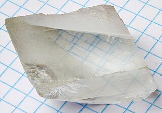
Birefringence is the optical property of a material having a refractive index that depends on the polarization and propagation direction of light. These optically anisotropic materials are described as birefringent or birefractive. The birefringence is often quantified as the maximum difference between refractive indices exhibited by the material. Crystals with non-cubic crystal structures are often birefringent, as are plastics under mechanical stress.

Stress–strain analysis is an engineering discipline that uses many methods to determine the stresses and strains in materials and structures subjected to forces. In continuum mechanics, stress is a physical quantity that expresses the internal forces that neighboring particles of a continuous material exert on each other, while strain is the measure of the deformation of the material.

The Kerr effect, also called the quadratic electro-optic (QEO) effect, is a change in the refractive index of a material in response to an applied electric field. The Kerr effect is distinct from the Pockels effect in that the induced index change for the Kerr effect is directly proportional to the square of the electric field instead of varying linearly with it. All materials show a Kerr effect, but certain liquids display it more strongly than others. The Kerr effect was discovered in 1875 by Scottish physicist John Kerr.

<span class="mw-page-title-main">Ellipsometry</span> Optical technique for characterizing thin films

Ellipsometry is an optical technique for investigating the dielectric properties of thin films. Ellipsometry measures the change of polarization upon reflection or transmission and compares it to a model.

<span class="mw-page-title-main">Polarimetry</span> Measurement and interpretation of the polarization of transverse waves

Polarimetry is the measurement and interpretation of the polarization of transverse waves, most notably electromagnetic waves, such as radio or light waves. Typically polarimetry is done on electromagnetic waves that have traveled through or have been reflected, refracted or diffracted by some material in order to characterize that object.

<span class="mw-page-title-main">Delamination</span> Mode of failure for which a material fractures into layers

Delamination is a mode of failure where a material fractures into layers. A variety of materials, including laminate composites and concrete, can fail by delamination. Processing can create layers in materials, such as steel formed by rolling and plastics and metals from 3D printing which can fail from layer separation. Also, surface coatings, such as paints and films, can delaminate from the coated substrate.

<span class="mw-page-title-main">Orthotropic material</span>

In material science and solid mechanics, orthotropic materials have material properties at a particular point which differ along three orthogonal axes, where each axis has twofold rotational symmetry. These directional differences in strength can be quantified with Hankinson's equation.

A photoelastic modulator (PEM) is an optical device used to modulate the polarization of a light source. The photoelastic effect is used to change the birefringence of the optical element in the photoelastic modulator.

<span class="mw-page-title-main">Shear band</span>

A shear band is a narrow zone of intense shearing strain, usually of plastic nature, developing during severe deformation of ductile materials. As an example, a soil specimen is shown in Fig. 1, after an axialsymmetric compression test. Initially the sample was cylindrical in shape and, since symmetry was tried to be preserved during the test, the cylindrical shape was maintained for a while during the test and the deformation was homogeneous, but at extreme loading two X-shaped shear bands had formed and the subsequent deformation was strongly localized.

<span class="mw-page-title-main">Acousto-optics</span> The study of sound and light interaction

Acousto-optics is a branch of physics that studies the interactions between sound waves and light waves, especially the diffraction of laser light by ultrasound through an ultrasonic grating.

<span class="mw-page-title-main">Viscosity</span> Resistance of a fluid to shear deformation

The viscosity of a fluid is a measure of its resistance to deformation at a given rate. For liquids, it corresponds to the informal concept of "thickness": for example, syrup has a higher viscosity than water. Viscosity is defined scientifically as a force multiplied by a time divided by an area. Thus its SI units are newton-seconds per square meter, or pascal-seconds.

Brillouin spectroscopy is an empirical spectroscopy technique which allows the determination of elastic moduli of materials. The technique uses inelastic scattering of light when it encounters acoustic phonons in a crystal, a process known as Brillouin scattering, to determine phonon energies and therefore interatomic potentials of a material. The scattering occurs when an electromagnetic wave interacts with a density wave, photon-phonon scattering.

<span class="mw-page-title-main">JCMsuite</span> Simulation software

JCMsuite is a finite element analysis software package for the simulation and analysis of electromagnetic waves, elasticity and heat conduction. It also allows a mutual coupling between its optical, heat conduction and continuum mechanics solvers. The software is mainly applied for the analysis and optimization of nanooptical and microoptical systems. Its applications in research and development projects include dimensional metrology systems, photolithographic systems, photonic crystal fibers, VCSELs, Quantum-Dot emitters, light trapping in solar cells, and plasmonic systems. The design tasks can be embedded into the high-level scripting languages MATLAB and Python, enabling a scripting of design setups in order to define parameter dependent problems or to run parameter scans.

Geometrically necessary dislocations are like-signed dislocations needed to accommodate for plastic bending in a crystalline material. They are present when a material's plastic deformation is accompanied by internal plastic strain gradients. They are in contrast to statistically stored dislocations, with statistics of equal positive and negative signs, which arise during plastic flow from multiplication processes like the Frank-Read source.

References

  1. Brewster, David (1815). "Experiments on the depolarisation of light as exhibited by various mineral, animal, and vegetable bodies, with a reference of the phenomena to the general principles of polarisation". Philosophical Transactions of the Royal Society of London. 105: 29–53. doi: 10.1098/rstl.1815.0004 .
  2. Brewster, David (1816). "On the communication of the structure of doubly refracting crystals to glass, muriate of soda, fluor spar, and other substances, by mechanical compression and dilatation". Philosophical Transactions of the Royal Society of London. 106: 156–178. doi:10.1098/rstl.1816.0011. S2CID   108782967.
  3. Fresnel, Augustin (1822). "Note sur la double réfraction du verre comprimé". Annales de Chimie et de Physique. Série 2. 20: 376–83.
    • Reprinted in H. de Senarmont, E. Verdet, and L. Fresnel (eds.), Oeuvres complètes d'Augustin Fresnel, vol. 1 (1866), pp. 713–18
    • Translated as Fresnel, Augustin-Jean (2021). "Note on the double refraction of compressed glass". Translated by Putland, Gavin Richard. doi:10.5281/zenodo.4706835.{{cite journal}}: Cite journal requires |journal= (help)
  4. Leven, M. M.; Frocht, M. M., eds. (1969). "Vita Max Mark Frocht". Photoelasticity. Pergamon. pp. xi–xii. doi:10.1016/B978-0-08-012998-3.50005-7. ISBN   978-0-08-012998-3.
  5. Pockels, F. (1890). "Ueber die durch einseitigen Druck hervorgerufene Doppelbrechung regulärer Krystalle, speciell von Steinsalz und Sylvin". Annalen der Physik und Chemie. 275 (3): 440–469. Bibcode:1890AnP...275..440P. doi:10.1002/andp.18902750313.
  6. Nelson, D. F.; Lax, M. (1970). "New Symmetry for Acousto-Optic Scattering". Physical Review Letters. 24 (8): 379–380. Bibcode:1970PhRvL..24..379N. doi:10.1103/PhysRevLett.24.379.
  7. Frocht, M.M., Photoelasticity. J. Wiley and Sons, London, 1965
  8. Ajovalasit, A.; Petrucci, G.; Scafidi, M. (2012). "RGB photoelasticity applied to the analysis of membrane residual stress in glass". Measurement Science and Technology. 23 (2): 025601. Bibcode:2012MeScT..23b5601A. doi:10.1088/0957-0233/23/2/025601. hdl: 10447/61842 . S2CID   53600215.
  9. Kramer, Sharlotte; Beiermann, Brett; Davis, Douglas; Sottos, Nancy; White, Scott; Moore, Jeffrey (2013). "Characterization of Mechanochemically Active Polymers Using Combined Photoelasticity and Fluorescence Measurements". Application of Imaging Techniques to Mechanics of Materials and Structures, Volume 4. Conference Proceedings of the Society for Experimental Mechanics Series. pp. 167–178. doi:10.1007/978-1-4419-9796-8_21. ISBN   978-1-4419-9528-5.
  10. Fernandes, Cláudio P.; Glantz, Per-Olof J.; Svensson, Stig A.; Bergmark, Anders (2003). "Reflection photoelasticity: A new method for studies of clinical mechanics in prosthetic dentistry". Dental Materials. 19 (2): 106–117. doi:10.1016/s0109-5641(02)00019-2. PMID   12543116.
  11. Bigoni, Davide; Noselli, Giovanni (2010). "Localized stress percolation through dry masonry walls. Part I – Experiments". European Journal of Mechanics - A/Solids. 29 (3): 291–298. Bibcode:2010EuJMA..29..291B. doi:10.1016/j.euromechsol.2009.10.009.
  12. Bigoni, Davide; Noselli, Giovanni (2010). "Localized stress percolation through dry masonry walls. Part II – Modelling". European Journal of Mechanics - A/Solids. 29 (3): 299–307. Bibcode:2010EuJMA..29..299B. doi:10.1016/j.euromechsol.2009.10.013.
  13. Bigoni, D. (2012). Nonlinear Solid Mechanics: Bifurcation Theory and Material Instability. Cambridge University Press. ISBN   9781107025417.
  14. Noselli, G.; Dal Corso, F.; Bigoni, D. (2010). "The stress intensity near a stiffener disclosed by photoelasticity". International Journal of Fracture. 166 (1–2): 91–103. doi:10.1007/s10704-010-9502-9. S2CID   56221414.
  15. Shukla, A. (2001). "High-speed fracture studies on bimaterial interfaces using photoelasticity—a review". The Journal of Strain Analysis for Engineering Design. 36 (2): 119–142. doi:10.1243/0309324011512658. S2CID   137504535.
  16. Ayatollahi, M.R.; Mirsayar, M.M.; Dehghany, M. (2011). "Experimental determination of stress field parameters in bi-material notches using photoelasticity". Materials & Design. 32 (10): 4901–4908. doi:10.1016/j.matdes.2011.06.002.
  17. J. F. Nye, "Physical Properties of Crystals: Their Representation by Tensors and Matrices", Oxford University Press, 1957.
  18. R. E. Newnham, "Properties of Materials: Anisotropy, Symmetry, Structure", Oxford University Press, 2005.
  19. Dally, J.W. and Riley, W.F., Experimental Stress Analysis, 3rd edition, McGraw-Hill Inc., 1991
  20. Ramesh, K., Digital Photoelasticity, Springer, 2000
  21. Solaguren-Beascoa Fernández, M.; Alegre Calderón, J. M.; Bravo Díez, P. M.; Cuesta Segura, I. I. (2010). "Stress-separation techniques in photoelasticity: A review". The Journal of Strain Analysis for Engineering Design. 45: 1–17. doi:10.1243/03093247JSA583. S2CID   208518298.