Automatic fuze that detonates an explosive device based on predetermined distance
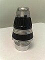
Proximity fuze MK53 removed from shell, circa 1950s
A proximity fuze (also VT fuze[1][2][3]) is a fuze that detonates an explosive device automatically when it approaches within a certain distance of its target. Proximity fuzes are designed for elusive military targets such as airplanes and missiles, as well as ships at sea and ground forces. This sophisticated trigger mechanism may increase lethality by 5 to 10 times compared to the common contact fuze or timed fuze.[4][5]
Before the invention of the proximity fuze, detonation was induced by direct contact, a timer set at launch, or an altimeter. All of these earlier methods have disadvantages. The probability of a direct hit on a small moving target is low; a shell that just misses the target will not explode. A time- or height-triggered fuze requires good prediction by the gunner and accurate timing by the fuze. If either is wrong, then even accurately aimed shells may explode harmlessly before reaching the target or after passing it. At the start of The Blitz, it was estimated that it took 20,000 rounds to shoot down a single aircraft;[6] other estimates put the figure as high as 100,000[7] or as low as 2,500.[8] With a proximity fuze, the shell or missile need only pass close by the target at some time during its flight. The proximity fuze makes the problem simpler than the previous methods.
Proximity fuzes are also useful for producing air bursts against ground targets. A contact fuze would explode when it hit the ground; it would not be very effective at scattering shrapnel. A timer fuze can be set to explode a few meters above the ground but the timing is vital and usually requires observers to provide information for adjusting the timing. Observers may not be practical in many situations, the ground may be uneven, and the practice is slow in any event. Proximity fuzes fitted to such weapons as artillery and mortar shells solve this problem by having a range of set burst heights [e.g. 2,4 or 10m (7,13 or 33ft)] above ground that are selected by gun crews. The shell bursts at the appropriate height above ground.
World War II
The idea of a proximity fuse had long been considered militarily useful. Several ideas had been considered, including optical systems that shone a light, sometimes infrared, and triggered when the reflection reached a certain threshold, various ground-triggered means using radio signals, and capacitive or inductive methods similar to a metal detector. All of these suffered from the large size of pre-WWII electronics and their fragility, as well as the complexity of the required circuitry.
British military researchers at the Telecommunications Research Establishment (TRE) Samuel Curran, William Butement, Edward Shire, and Amherst Thomson conceived of the idea of a proximity fuze in the early stages of World War II.[9] Their system involved a small, short range, Doppler radar. British tests were then carried out with "unrotated projectiles" (the contemporary British term for unguided rockets). However, British scientists were uncertain whether a fuze could be developed for anti-aircraft shells, which had to withstand much higher accelerations than rockets. The British shared a wide range of possible ideas for designing a fuze, including a photoelectric fuze and a radio fuze, with United States during the Tizard Mission in late 1940. To work in shells, a fuze needed to be miniaturized, survive the high acceleration of cannon launch, and be reliable.[10]
The National Defense Research Committee assigned the task to the physicist Merle Tuve at the Department of Terrestrial Magnetism. Also eventually pulled in were researchers from the National Bureau of Standards (this research unit of NBS later became part of the Army Research Laboratory). Work was split in 1942, with Tuve's group working on proximity fuzes for shells, while the National Bureau of Standards researchers focused on the technically easier task of bombs and rockets. Work on the radio shell fuze was completed by Tuve's group, known as Section T, at The Johns Hopkins University Applied Physics Lab (APL).[11][12] Over 100 American companies were mobilized to build some 20 million shell fuzes.[13]
The proximity fuze was one of the most important technological innovations of World War II. It was so important that it was a secret guarded to a similar level as the atom bomb project or D-Day invasion.[14][15][16] Admiral Lewis Strauss wrote that,
One of the most original and effective military developments in World War II was the proximity, or 'VT', fuze. It found use in both the Army and the Navy, and was employed in the defense of London. While no one invention won the war, the proximity fuze must be listed among the very small group of developments, such as radar, upon which victory very largely depended.[17]
The fuze was later found to be able to detonate artillery shells in air bursts, greatly increasing their anti-personnel effects.[18]
In Germany, more than 30 (perhaps as many as 50)[19] different proximity fuze designs were developed, or researched, for anti-aircraft use, but none saw service.[10] These included acoustic fuzes triggered by engine sound, one developed by Rheinmetall-Borsig based on electrostatic fields, and radio fuzes. In mid-November 1939, a German neon lamp tube and a design of a prototype proximity fuze based on capacitive effects was received by British Intelligence as part of the Oslo Report.
In the post-World War II era, a number of new proximity fuze systems were developed, using radio, optical, and other detection methods. A common form used in modern air-to-air weapons uses a laser as an optical source and time-of-flight for ranging.[20]
Design in the UK
The first reference to the concept of radar in the UK was made by W. A. S. Butement and P. E. Pollard, who constructed a small breadboard model of a pulsed radar in 1931. They suggested the system would be useful for coast artillery units to accurately measure the range to shipping even at night. The War Office was not interested in the concept, and told the two to work on other issues.[21][22]
In 1936, the Air Ministry took over Bawdsey Manor in Suffolk to further develop their prototype radar systems that emerged the next year as Chain Home. The Army was suddenly extremely interested in the topic of radar, and sent Butement and Pollard to Bawdsey to form what became known as the "Army Cell". Their first project was a revival of their original work on coast defense, but they were soon told to start a second project to develop a range-only radar to aid anti-aircraft guns.[23]
As these projects moved from development into prototype form in the late 1930s, Butement turned his attention to other concepts, and among these was the idea of a proximity fuze:
...Into this stepped W. A. S. Butement, designer of radar sets CD/CHL and GL, with a proposal on 30 October 1939 for two kinds of radio fuze: (1) a radar set would track the projectile, and the operator would transmit a signal to a radio receiver in the fuze when the range, the difficult quantity for the gunners to determine, was the same as that of the target and (2) a fuze would emit high-frequency radio waves that would interact with the target and produce, as a consequence of the high relative speed of target and projectile, a Doppler-frequency signal sensed in the oscillator.[24]
In May 1940, a formal proposal from Butement, Edward Shire, and Amherst Thomson was sent to the British Air Defence Establishment based on the second of the two concepts.[9] A breadboard circuit was constructed, and the concept was tested in the laboratory by moving a sheet of tin at various distances. Early field testing connected the circuit to a thyratron trigger operating a tower-mounted camera which photographed passing aircraft to determine distance of fuze function.
Prototype fuzes were then constructed in June 1940, and installed in "unrotated projectiles", the British cover name for solid-fueled rockets, and fired at targets supported by balloons.[9] Rockets have relatively low acceleration and no spin creating centrifugal force, so the stresses on the delicate electronic fuze are relatively benign. It was understood that the limited application was not ideal; a proximity fuze would be useful on all types of artillery and especially anti-aircraft artillery, but those had very high accelerations.
As early as September 1939, John Cockcroft began a development effort at Pye Ltd. to develop thermionic valves (electron tubes) capable of withstanding these much greater forces.[25] Pye's research was transferred to the United States as part of the technology package delivered by the Tizard Mission when the United States entered the war. Pye's group was apparently unable to get their rugged pentodes to function reliably under high pressures until 6 August 1941, which was after the successful tests by the American group.[26][27]
Looking for a short-term solution to the valve problem, in 1940 the British ordered 20,000 miniature electron tubes intended for use in hearing aids from Western Electric Company and Radio Corporation of America. An American team under Admiral Harold G. Bowen, Sr. correctly deduced that they were meant for experiments with proximity fuzes for bombs and rockets.[10]
Prior to and following receipt of circuitry designs from the British, various experiments were carried out by Richard B. Roberts, Henry H. Porter, and Robert B. Brode under the direction of NDRC Section T Chairman Merle Tuve.[9] Tuve's group was known as Section T, which was located at APL throughout the war.[29] As Tuve later put it in an interview: "We heard some rumors of circuits they were using in the rockets over in England, then they gave us the circuits, but I had already articulated the thing into the rockets, the bombs and shell."[27][30] As Tuve understood, the circuitry of the fuze was rudimentary. In his words, "The one outstanding characteristic in this situation is the fact that success of this type of fuze is not dependent on a basic technical idea–all of the ideas are simple and well known everywhere."[27] The critical work of adapting the fuze for anti-aircraft shells was done in the United States, not in England.[31] Tuve said that despite being pleased by the outcome of the Butement et al. vs. Varian patent suit, which affirmed that the fuze was a UK invention and thereby saved the U.S. Navy millions of dollars by waiving royalty fees, the fuze design delivered by the Tizard Mission was "not the one we made to work!".[32]
A key improvement was introduced by Lloyd Berkner, who developed a system using separate transmitter and receiver circuits. In December 1940, Tuve invited Harry Diamond and Wilbur S. Hinman, Jr, of the United States National Bureau of Standards (NBS) to investigate Berkner's improved fuze and develop a proximity fuze for rockets and bombs to use against German Luftwaffe aircraft.[9][33][34]
In just two days, Diamond was able to come up with a new fuze design and managed to demonstrate its feasibility through extensive testing at the Naval Proving Ground at Dahlgren, Virginia.[35][36] On 6 May 1941, the NBS team built six fuzes which were placed in air-dropped bombs and successfully tested over water.[9]
Given their previous work on radio and radiosondes at NBS, Diamond and Hinman developed the proximity fuze which employed the Doppler effect of reflected radio waves.[34][37][38] The use of the Doppler effect developed by this group was later incorporated in all radio proximity fuzes for bomb, rocket, and mortar applications.[33] Later, the Ordnance Development Division of the National Bureau of Standards (which became the Harry Diamond Laboratories – and later merged into the Army Research Laboratory – in honor of its former chief in subsequent years) developed the first automated production techniques for manufacturing radio proximity fuzes at low cost.[38]
While working for a defense contractor in the mid-1940s, Soviet spy Julius Rosenberg stole a working model of an American proximity fuze and delivered it to Soviet intelligence.[39] It was not a fuze for anti-aircraft shells, the most valuable type.[40]
In the US, NDRC focused on radio fuzes for use with anti-aircraft artillery, where acceleration was up to 20,000g, compared to about 100g for rockets and much less for dropped bombs.[41] In addition to extreme acceleration, artillery shells were spun by the rifling of the gun barrels to close to 30,000 rpm, creating immense centrifugal force. Working with Western Electric Company and Raytheon Company, miniature hearing-aid tubes were modified to withstand this extreme stress. The T-3 fuze had a 52% success against a water target when tested in January, 1942. The United States Navy accepted that failure rate. A simulated battle conditions test was started on 12 August 1942. Gun batteries aboard cruiser USSCleveland(CL-55) tested proximity-fuzed ammunition against radio-controlled drone aircraft targets over Chesapeake Bay. The tests were to be conducted over two days, but the testing stopped when drones were destroyed early on the first day. The three drones were destroyed with just four projectiles.[9][42]
A particularly successful application was the 90mm shell with VT fuze with the SCR-584 automatic tracking radar and the M9 Gun Directorfire control computer. The combination of these three inventions was successful in shooting down many V-1 flying bombs aimed at London and Antwerp, otherwise difficult targets for anti-aircraft guns due to their small size and high speed.
VT (Variable Time)
The Allied fuze used constructive and destructive interference to detect its target.[43] The design had four or five electron tubes.[44] One tube was an oscillator connected to an antenna; it functioned as both a transmitter and an autodyne detector (receiver). When the target was far away, little of the oscillator's transmitted energy would be reflected to the fuze. When a target was nearby, it would reflect a significant portion of the oscillator's signal. The amplitude of the reflected signal corresponded to the closeness of the target.[notes 1] This reflected signal would affect the oscillator's plate current, thereby enabling detection.
However, the phase relationship between the oscillator's transmitted signal and the signal reflected from the target varied depended on the round trip distance between the fuze and the target. When the reflected signal was in phase, the oscillator amplitude would increase and the oscillator's plate current would also increase. But when the reflected signal was out of phase then the combined radio signal amplitude would decrease, which would decrease the plate current. So the changing phase relationship between the oscillator signal and the reflected signal complicated the measurement of the amplitude of that small reflected signal.
This problem was resolved by taking advantage of the change in frequency of the reflected signal. The distance between the fuze and the target was not constant but rather constantly changing due to the high speed of the fuze and any motion of the target. When the distance between the fuze and the target changed rapidly, then the phase relationship also changed rapidly. The signals were in-phase one instant and out-of-phase a few hundred microseconds later. The result was a heterodyne beat frequency which corresponded to the velocity difference. Viewed another way, the received signal frequency was Doppler-shifted from the oscillator frequency by the relative motion of the fuze and target. Consequently, a low frequency signal, corresponding to the frequency difference between the oscillator and the received signal, developed at the oscillator's plate terminal. Two of the four tubes in the VT fuze were used to detect, filter, and amplify this low frequency signal. Note here that the amplitude of this low frequency 'beat' signal corresponds to the amplitude of the signal reflected from the target. If the amplified beat frequency signal's amplitude was large enough, indicating a nearby object, then it triggered the fourth tube – a gas-filled thyratron. Upon being triggered, the thyratron conducted a large current that set off the electrical detonator.
In order to be used with gun projectiles, which experience extremely high acceleration and centrifugal forces, the fuze design also needed to utilize many shock-hardening techniques. These included planar electrodes, and packing the components in wax and oil to equalize the stresses.[citation needed] To prevent premature detonation, the inbuilt battery that armed the shell had a several millisecond delay before its electrolytes were activated, giving the projectile time to clear the area of the gun.[45]
The designation VT means 'variable time'.[46] Captain S. R. Shumaker, Director of the Bureau of Ordnance's Research and Development Division, coined the term to be descriptive without hinting at the technology.[47]
Development
The anti-aircraft artillery range at Kirtland Air Force Base in New Mexico was used as one of the test facilities for the proximity fuze, where almost 50,000 test firings were conducted from 1942 to 1945.[48] Testing also occurred at Aberdeen Proving Ground in Maryland, where about 15,000 bombs were dropped.[37] Other locations include Ft. Fisher in North Carolina and Blossom Point, Maryland.
First large scale production of tubes for the new fuzes[9] was at a General Electric plant in Cleveland, Ohio formerly used for manufacture of Christmas-tree lamps. Fuze assembly was completed at General Electric plants in Schenectady, New York and Bridgeport, Connecticut.[50] Once inspections of the finished product were complete, a sample of the fuzes produced from each lot was shipped to the National Bureau of Standards, where they were subjected to a series of rigorous tests at the specially built Control Testing Laboratory.[37] These tests included low- and high-temperature tests, humidity tests, and sudden jolt tests.
By 1944, a large proportion of the American electronics industry concentrated on making the fuzes. Procurement contracts increased from US$60 million in 1942, to $200 million in 1943, to $300 million in 1944 and were topped by $450 million in 1945. As volume increased, efficiency came into play and the cost per fuze fell from $732 in 1942 to $18 in 1945. This permitted the purchase of over 22 million fuzes for approximately one billion dollars ($14.6 billion in 2021 USD[51]). The main suppliers were Crosley, RCA, Eastman Kodak, McQuay-Norris and Sylvania. There were also over two thousand suppliers and subsuppliers, ranging from powder manufacturers to machine shops.[52][53] It was among the first mass-production applications of printed circuits.[54]
It was important in defense from Japanese kamikaze attacks in the Pacific. Bush estimated a sevenfold increase in the effectiveness of 5-inch anti-aircraft artillery with this innovation.[56]
It was an important part of the radar-controlled anti-aircraft batteries that finally neutralized the German V-1 attacks on England.[56]
It was used in Europe starting in the Battle of the Bulge where it was very effective in artillery shells fired against German infantry formations, and changed the tactics of land warfare.
At first the fuzes were only used in situations where they could not be captured by the Germans. They were used in land-based artillery in the South Pacific in 1944. Also in 1944, fuzes were allocated to the British Army's Anti-Aircraft Command, that was engaged in defending Britain against the V-1 flying bomb. As most of the British heavy anti-aircraft guns were deployed in a long, thin coastal strip (leaving inland free for fighter interceptors), dud shells fell into the sea, safely out of reach of capture. Over the course of the German V-1 campaign, the proportion of flying bombs that were destroyed flying through the coastal gun belt rose from 17% to 74%, reaching 82% during one day. A minor problem encountered by the British was that the fuze was sensitive enough to detonate the shell if it passed too close to a seabird and a number of seabird "kills" were recorded.[57]
The Pentagon refused to allow the Allied field artillery use of the fuzes in 1944, although the United States Navy fired proximity-fuzed anti-aircraft shells in the July 1943 Battle of Gela during the invasion of Sicily.[58] After General Dwight D. Eisenhower demanded he be allowed to use the fuzes, 200,000 shells with VT fuzes (code named "POZIT"[59]) were used in the Battle of the Bulge in December 1944. They made the Allied heavy artillery far more devastating, as all the shells now exploded just before hitting the ground.[60] German divisions were caught out in open as they had felt safe from timed fire because it was thought that the bad weather would prevent accurate observation. U.S. General George S. Patton credited the introduction of proximity fuzes with saving Liège and stated that their use required a revision of the tactics of land warfare.[61]
Bombs and rockets fitted with radio proximity fuzes were in limited service with both the USAAF and USN at the end of WWII. The main targets for these proximity fuze detonated bombs and rockets were anti-aircraft emplacements and airfields.[62]
Sensor types
Radio
Radio frequency sensing (radar) is the main sensing principle for artillery shells.
The device described in World War II patent[63] works as follows: The shell contains a micro-transmitter which uses the shell body as an antenna and emits a continuous wave of roughly 180–220MHz. As the shell approaches a reflecting object, an interference pattern is created. This pattern changes with shrinking distance: every half wavelength in distance (a half wavelength at this frequency is about 0.7meters), the transmitter is in or out of resonance. This causes a small cycling of the radiated power and consequently the oscillator supply current of about 200–800Hz, the Doppler frequency. This signal is sent through a band-pass filter, amplified, and triggers the detonation when it exceeds a given amplitude.[citation needed]
Optical
Optical sensing was developed in 1935, and patented in the United Kingdom in 1936, by a Swedish inventor, probably Edward W. Brandt, using a petoscope. It was first tested as a part of a detonation device for bombs that were to be dropped over bomber aircraft, part of the UK's Air Ministry's "bombs on bombers" concept. It was considered (and later patented by Brandt) for use with anti-aircraft missiles fired from the ground. It used then a toroidal lens, that concentrated all light from a plane perpendicular to the missile's main axis onto a photocell. When the cell current changed a certain amount in a certain time interval, the detonation was triggered.
Some modern air-to-air missiles (e.g., the ASRAAM and AA-12 Adder) use lasers to trigger detonation. They project narrow beams of laser light perpendicular to the flight of the missile. As the missile cruises towards its target the laser energy simply beams out into space. As the missile passes its target some of the energy strikes the target and is reflected to the missile, where detectors sense it and detonate the warhead.
Acoustic
Acoustic proximity fuzes are actuated by the acoustic emissions from a target (example an aircraft's engine or ship's propeller). Actuation can be either through an electronic circuit coupled to a microphone, or hydrophone, or mechanically using a resonating vibratory reed connected to diaphragm tone filter. [64][65]
During WW2, the Germans had at least five acoustic fuzes for anti-aircraft use under development, though none saw operational service. The most developmentally advanced of the German acoustic fuze designs was the Rheinmetall-Borsig Kranich (German for Crane) which was a mechanical device utilizing a diaphragm tone filter sensitive to frequencies between 140 and 500Hz connected to a resonating vibratory reed switch used to fire an electrical igniter. The Schmetterling, Enzian, Rheintochter and X4guided missiles were all designed for use with the Kranich acoustic proximity fuze. [64][66]
During WW2, the National Defense Research Committee (NDRC) investigated the use of acoustic proximity fuzes for anti-aircraft weapons but concluded that there were more promising technological approaches. The NDRC research highlighted the speed of sound as a major limitation in the design and use of acoustic fuzes, particularly in relation to missiles and high-speed aircraft.[65]
Hydroacoustic influence is widely used as a detonation mechanism for naval mines and torpedoes. A ship's propeller rotating in water produces a powerful hydroacoustic noise which can be picked up using a hydrophone and used for homing and detonation. Influence firing mechanisms often use a combination of acoustic and magnetic induction receivers.[67][68]
Magnetic
German World War II magnetic mine that landed on the ground instead of the water.
Magnetic sensing can only be applied to detect huge masses of iron such as ships. It is used in mines and torpedoes. Fuzes of this type can be defeated by degaussing, using non-metal hulls for ships (especially minesweepers) or by magnetic induction loops fitted to aircraft or towed buoys.
Pressure
Some naval mines use pressure fuzes which are able to detect the pressure wave of a ship passing overhead. Pressure sensors are usually used in combination with other fuze detonation technologies such as acoustic and magnetic induction.[68]
During WW2, pressure activated fuzes were developed for sticks (or trains) of bombs to create above ground airbursts. The first bomb in the stick was fitted with an impact fuze while the other bombs were fitted with pressure sensitive diaphragm actuated detonators. The blast from the first bomb was used to trigger the fuze of the second bomb which would explode above ground and in this turn would detonate the third bomb with the process repeated all the way till the last bomb in the string. Due to the forward speed of the bomber, bombs fitted with pressure detonators would all explode at about the same height above ground along a horizontal trajectory. This design was used in both the British No.44 "Pistol" and the German Rheinmetall-Borsig BAZ 55A fuzes.[64][65]
↑ The return signal is inversely proportional to the fourth power of the distance.
Related Research Articles
Artillery are ranged weapons that launch munitions far beyond the range and power of infantry firearms. Early artillery development focused on the ability to breach defensive walls and fortifications during sieges, and led to heavy, fairly immobile siege engines. As technology improved, lighter, more mobile field artillery cannons developed for battlefield use. This development continues today; modern self-propelled artillery vehicles are highly mobile weapons of great versatility generally providing the largest share of an army's total firepower.
Anti-aircraft warfare is the counter to aerial warfare and it includes "all measures designed to nullify or reduce the effectiveness of hostile air action". It includes surface based, subsurface, and air-based weapon systems, associated sensor systems, command and control arrangements, and passive measures. It may be used to protect naval, ground, and air forces in any location. However, for most countries, the main effort has tended to be homeland defence. Missile defence is an extension of air defence, as are initiatives to adapt air defence to the task of intercepting any projectile in flight.
A shell, in a military context, is a projectile whose payload contains an explosive, incendiary, or other chemical filling. Originally it was called a bombshell, but "shell" has come to be unambiguous in a military context. A shell can hold a tracer.
William Sterling Parsons was an American naval officer who worked as an ordnance expert on the Manhattan Project during World War II. He is best known for being the weaponeer on the Enola Gay, the aircraft which dropped an atomic bomb on Hiroshima, Japan, in 1945. To avoid the possibility of a nuclear explosion if the aircraft crashed and burned on takeoff, he decided to arm the bomb in flight. While the aircraft was en route to Hiroshima, Parsons climbed into the cramped and dark bomb bay, and inserted the powder charge and detonator. He was awarded the Silver Star for his part in the mission.
An air burst or airburst is the detonation of an explosive device such as an anti-personnel artillery shell or a nuclear weapon in the air instead of on contact with the ground or target. The principal military advantage of an air burst over a ground burst is that the energy from the explosion is distributed more evenly over a wider area; however, the peak energy is lower at ground zero.
The Oslo Report was one of the most spectacular leaks in the history of military intelligence. Written by German mathematician and physicist Hans Ferdinand Mayer on 1 and 2 November 1939 during a business trip to Oslo, Norway, it described several German weapons, some in service and others being developed. Mayer mailed the report anonymously in the form of two letters to the British Embassy in Oslo, where they were passed on to MI6 in London for further analysis, providing an invaluable resource to the British in developing counter-measures, especially to navigational and targeting radars and contributed to the British winning the Battle of Britain.
A guided bomb is a precision-guided munition designed to achieve a smaller circular error probable (CEP).
The SCR-584 was an automatic-tracking microwave radar developed by the MIT Radiation Laboratory during World War II. It was one of the most advanced ground-based radars of its era, and became one of the primary gun laying radars used worldwide well into the 1950s. A trailer-mounted mobile version was the SCR-784.
The Iowa-class battleships are the most heavily armed warships the United States Navy has ever put to sea, due to the continual development of their onboard weaponry. The first Iowa-class ship was laid down in June 1940; in their World War II configuration, each of the Iowa-class battleships had a main battery of 16-inch (406 mm) guns that could hit targets nearly 20 statute miles (32 km) away with a variety of artillery shells designed for anti-ship or bombardment work. The secondary battery of 5-inch (127 mm) guns could hit targets nearly 9 statute miles (14 km) away with solid projectiles or proximity fuzed shells, and was effective in an anti-aircraft role as well. Each of the four battleships carried a wide array of 20 mm and 40 mm anti-aircraft guns for defense against enemy aircraft.
Ammunition is the material fired, scattered, dropped, or detonated from any weapon or weapon system. Ammunition is both expendable weapons and the component parts of other weapons that create the effect on a target.
In military munitions, a fuze is the part of the device that initiates its function. In some applications, such as torpedoes, a fuze may be identified by function as the exploder. The relative complexity of even the earliest fuze designs can be seen in cutaway diagrams.
A precision-guided munition (PGM), also called a smart weapon, smart munition, or smart bomb, is a guided munition intended to hit a specific target, to minimize collateral damage and increase lethality against intended targets. During the Persian Gulf War guided munitions accounted for only 9% of weapons fired, but accounted for 75% of all successful hits. Despite guided weapons generally being used on more difficult targets, they were still 35 times more likely to destroy their targets per weapon dropped.
An artillery fuze or fuse is the type of munition fuze used with artillery munitions, typically projectiles fired by guns, howitzers and mortars. A fuze is a device that initiates an explosive function in a munition, most commonly causing it to detonate or release its contents, when its activation conditions are met. This action typically occurs a preset time after firing, or on physical contact with or detected proximity to the ground, a structure or other target. Fuze, a variant of fuse, is the official NATO spelling.
William Alan Stewart Butement was a New Zealand-born British-Australian defence scientist and public servant. A native of New Zealand, he made extensive contributions to radar development in Great Britain during World War II, served as the first chief scientist for the Australian Defence Scientific Service, then ended his professional career with a research position in private business.
A contact fuze, impact fuze, percussion fuze or direct-action (D.A.) fuze (UK) is the fuze that is placed in the nose of a bomb or shell so that it will detonate on contact with a hard surface.
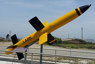
The SAM-N-2 Lark project was a solid-fuel boosted, liquid-fueled surface-to-air missile developed by the United States Navy to meet the kamikaze threat. It was developed as a crash program to introduce a medium-range defensive layer that would attack targets between the long-range combat air patrols and short-range anti-aircraft artillery. This produced a design with roughly 30 miles (48 km) maximum range and subsonic performance, suitable for attacks against Japanese aircraft.
The RSD 58 is an early production surface-to-air missile system developed by Contraves-Oerlikon in Switzerland from 1947. Test firings were made in Switzerland and Italy in 1958, and Japan placed a small order for training purposes, but the missile was not produced in high numbers. The missile system was developed from the earlier RSA Missile developed by the same companies.
In the field of weaponry, terminal guidance refers to any guidance system that is primarily or solely active during the "terminal phase", just before the weapon impacts its target. The term is generally used in reference to missile guidance systems, and specifically to missiles that use more than one guidance system through the missile's flight.
Funryu were a series of surface-to-air anti-aircraft missiles developed in Japan at the end of the Second World War. The missile's development in the late stages of the war was plagued by organizational problems and cancelled before becoming operational.
↑ Klein, Maury (2013). A Call to Arms: Mobilizing America for World War II. New York: Bloomsbury Press. pp.651–652, 838 n. 8. ISBN978-1-59691-607-4.
↑ Thompson, Harry C.; Mayo, Lida (1960), The Ordnance Department: Procurement and Supply, Washington, D.C., pp.123–124{{citation}}: CS1 maint: location missing publisher (link)
↑ Woodbury, David (1948), Battlefronts of Industry: Westinghouse in World War II, New York, pp.244–248{{citation}}: CS1 maint: location missing publisher (link)
↑ Parker, Dana T. (2013), Building Victory: Aircraft Manufacturing in the Los Angeles Area in World War II, Cypress, California, p.127, ISBN978-0-9897906-0-4{{citation}}: CS1 maint: location missing publisher (link)
1 2 Erickson, Andrew; Goldstein, Lyle; Murray, William (2009). Chinese Mine Warfare. Naval War College. pp.12–17. ISBN978-1-884733-63-5.
Bibliography
Baldwin, Ralph B. (1980), The Deadly Fuze: The Secret Weapon of World War II, San Rafael, CA: Presidio Press, ISBN978-0-89141-087-4 . Baldwin was a member of the (APL) team headed by Tuve that did most of the design work.
Gibbs, Jay (2004). "Question 37/00: Effectiveness of Shipboard Anti-Aircraft Fire". Warship International. XLI (1): 29. ISSN0043-0374.
Hogg, Ian V. (2002), British & American Artillery of World War Two (reviseded.), Greenhill Books, ISBN978-1-85367-478-5
Fuzes, Proximity, Electrical: Part One(PDF), Engineering Design Handbook: Ammunition Series, United States Army Materiel Command, July 1963, AMCP 706-211, archived from the original(PDF) on 29 March 2018, retrieved 26 January 2012
Fuzes, Proximity, Electrical: Part Two, Engineering Design Handbook: Ammunition Series, United States Army Materiel Command, AMCP 706-212
Fuzes, Proximity, Electrical: Part Three, Engineering Design Handbook: Ammunition Series, United States Army Materiel Command, AMCP 706-213
Fuzes, Proximity, Electrical: Part Four, Engineering Design Handbook: Ammunition Series, United States Army Materiel Command, AMCP 706-214
Fuzes, Proximity, Electrical: Part Five, Engineering Design Handbook: Ammunition Series, United States Army Materiel Command, August 1963, AMCP 706-215, archived from the original on 8 April 2013, retrieved 26 January 2012
US 3166015, Tuve, Merle A.&Roberts, Richard B.,"Radio Proximity Fuze",published 1965-01-19, assigned to United States of America
External links
Look up proximity fuze in Wiktionary, the free dictionary.
This page is based on this Wikipedia article Text is available under the CC BY-SA 4.0 license; additional terms may apply. Images, videos and audio are available under their respective licenses.