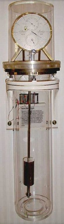
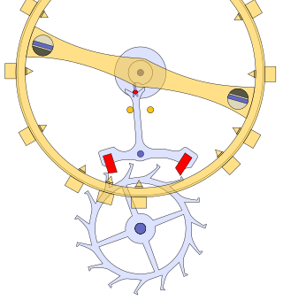
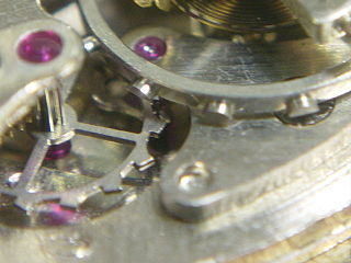
Riefler escapement used in the Clemens Riefler regulator clock, 1893. Shows the bearer (A'), knife edges (c), agate support surfaces (P), suspension spring (i), locking escape wheel (h), impulse escape wheel (H), and pallets (S,S').The Riefler precision pendulum clock No. 549, currently (2006) serving as the workshop regulator in the horological workshop of the Deutsches Museum.Side view, closeup of double escape wheel of Riefler No.549. This clock has clear synthetic ruby pallets. (Dial on the right side.)
The Riefler escapement is a mechanical escapement for precision pendulum clocks invented and patented[1] by German instrument maker Sigmund Riefler in 1889.[2] It was used in the astronomical regulator clocks made by his German firm Clemens Riefler from 1890 to 1965,[3] which were perhaps the most accurate all-mechanical pendulum clocks made.
An escapement is the mechanism in a mechanical clock that gives the pendulum precise impulses to keep it swinging, and allows the gear train to advance a set amount with each pendulum swing, moving the clock hands forward at a steady rate. The Riefler escapement was an improvement of the deadbeat escapement, the previous standard for precision clocks. In the deadbeat, the force to keep the pendulum swinging is applied by the teeth of the escape wheel sliding alternately against two angled pallets on arms attached to the pendulum. Therefore, slight variations in the friction of the pallets and in the torque from the escape wheel are passed on to the pendulum, disturbing its motion.
How it works
In the Riefler escapement, the energy required to keep the pendulum swinging is instead supplied by bending the short straight spring strip which suspends the pendulum.[4] The upper end of the suspension spring is not attached to a fixed support as in most clocks, but instead is attached to a heavy metal bearer, which pivots on two aligned knife-edges on its underside which rest on flat agate plates. The bending point of the suspension spring is in alignment with the line of contact of the knife-edges. When the pendulum passes its bottom point, the escape wheel is unlocked and pushes the bearer, and the bearer pivots suddenly on its knife edges by a small angle, flexing the spring. The spring is bent by a small amount in addition to that caused by the swing of the pendulum, and thus provides the impulse for the next swing. So the suspension spring is used for two functions: suspending the pendulum and giving it impulse.
The escapement has better performance than the deadbeat because the force from the pallets, with its variability, is applied not to the pendulum but to the bearer.[4] The escapement has no contact with the pendulum below the suspension spring. The pendulum is free of disturbance from the escape wheel for most of each swing and the only work it has to do is to unlock the escape wheel once per second. This operation is performed near the ideal place, at the center of each swing.
The Riefler escape wheel and pallets are of a special design. There are actually two escape wheels mounted on the same shaft and two surfaces on each of the two pallet pins. The front locking wheel has forward pointing teeth rather like a dead-beat escapement, and catches on the flat surface of the pallet to lock the wheel. The rear impulse wheel has teeth with a sloping surface facing the direction of rotation. The round part of each pallet is acted upon by this surface to give the impulse.
Riefler clocks
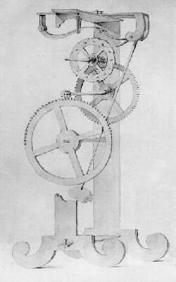
Riefler clock, NIST museum, Gaithersburg, Maryland, USA. 54 inches (134 cm) tall. This clock served as the first US time standard, from 1904 to 1929.
Clemens Riefler precision regulator clocks achieved accuracies of 10 milliseconds per day,[5][6] and were guaranteed to be within 30 milliseconds.[7] With over 600 made,[3] they were one of the most widely used astronomical regulators, and became the highest standard for timekeeping in the early 20th century. They were used worldwide in astronomical observatories, naval observatories, and as primary standards for electrical time dissemination services, which delivered time signals by telegraph wire. Riefler clocks had internal switch contacts for this purpose, which delivered a 1 Hz time signal to external equipment. The first time standard for the United States, provided by the Bureau of Standards (now NIST), was from 1904 to 1929 generated by Riefler clocks.[5]
In addition to the Riefler escapement, Riefler clocks' mechanism had several other innovations which were responsible for their accuracy. They were one of the first clocks to use a pendulum rod made of the low thermal expansion alloy invar, to prevent the pendulum from changing length with temperature changes, causing error. The most accurate models were mounted in a low pressure tank to eliminate the effect of changes in atmospheric pressure on the pendulum. They were powered by a gravity remontoire, a small weight which was wound up by an electric motor every 30 seconds, to eliminate the effect of changes in drive force on the mechanism.
"Riefler astronomical regulator No. 65". inventory no. 1998-1-0190a. History of Science Dept., Harvard Univ. Archived from the original on 2011-07-19. Retrieved 2008-05-31. Pictures of 1902 Riefler clock and its parts
Weinheimer, Peter (2000). "Detailed pictures of parts". Wiederentdeckung und Instandsetzung der Präzisionspendeluhr Riefler Nr. 711 (Rediscovery and repair of Riefler No. 711). radiophil.com. Archived from the original on 2023-02-05. Retrieved 2008-05-31.
"Clemens Riefler regulator, 1929". Precision Regulator Clocks Gallery, National Watch and Clock Museum. NAWCC (National Association of Watch and Clock Collectors). 2007. Archived from the original on 2007-10-29. Retrieved 2008-06-02. Closeups of 3 Riefler clocks and some technical information
"About Us". Riefler Industries, GmBH. 2007. Archived from the original on 2007-05-24. Retrieved 2008-06-02. Present day Riefler Co., does not make clocks
1 2 Sullivan, D.B. (2001). "Time and frequency measurement at NIST: The first 100 years". 2001 IEEE Int'l Frequency Control Symp. National Institute of Standards and Technology. doi:10.1109/FREQ.2001.956152. p.4-5
↑ "Clemens Riefler regulator, 1929". Precision Regulator Clocks Gallery, National Watch and Clock Museum. NAWCC (National Association of Watch and Clock Collectors). 2007. Retrieved 2008-06-02.
Related Research Articles
A pendulum clock is a clock that uses a pendulum, a swinging weight, as its timekeeping element. The advantage of a pendulum for timekeeping is that it is an approximate harmonic oscillator: It swings back and forth in a precise time interval dependent on its length, and resists swinging at other rates. From its invention in 1656 by Christiaan Huygens, inspired by Galileo Galilei, until the 1930s, the pendulum clock was the world's most precise timekeeper, accounting for its widespread use. Throughout the 18th and 19th centuries, pendulum clocks in homes, factories, offices, and railroad stations served as primary time standards for scheduling daily life, work shifts, and public transportation. Their greater accuracy allowed for the faster pace of life which was necessary for the Industrial Revolution. The home pendulum clock was replaced by less-expensive synchronous electric clocks in the 1930s and '40s. Pendulum clocks are now kept mostly for their decorative and antique value.
A pendulum is a device made of a weight suspended from a pivot so that it can swing freely. When a pendulum is displaced sideways from its resting, equilibrium position, it is subject to a restoring force due to gravity that will accelerate it back toward the equilibrium position. When released, the restoring force acting on the pendulum's mass causes it to oscillate about the equilibrium position, swinging back and forth. The time for one complete cycle, a left swing and a right swing, is called the period. The period depends on the length of the pendulum and also to a slight degree on the amplitude, the width of the pendulum's swing.
George Graham, FRS was an English clockmaker, inventor, and geophysicist, and a Fellow of the Royal Society.
The grasshopper escapement is a low-friction escapement for pendulum clocks invented by British clockmaker John Harrison around 1722. An escapement, part of every mechanical clock, is the mechanism that gives the clock's pendulum periodic pushes to keep it swinging, and each swing releases the clock's gears to move forward by a fixed amount, thus moving the hands forward at a steady rate. The grasshopper escapement was used in a few regulator clocks built during Harrison's time, and a few others over the years, but has never seen wide use. The term "grasshopper" in this connection, apparently from the kicking action of the pallets, first appears in the Horological Journal in the late 19th century.
An escapement is a mechanical linkage in mechanical watches and clocks that gives impulses to the timekeeping element and periodically releases the gear train to move forward, advancing the clock's hands. The impulse action transfers energy to the clock's timekeeping element to replace the energy lost to friction during its cycle and keep the timekeeper oscillating. The escapement is driven by force from a coiled spring or a suspended weight, transmitted through the timepiece's gear train. Each swing of the pendulum or balance wheel releases a tooth of the escapement's escape wheel, allowing the clock's gear train to advance or "escape" by a fixed amount. This regular periodic advancement moves the clock's hands forward at a steady rate. At the same time, the tooth gives the timekeeping element a push, before another tooth catches on the escapement's pallet, returning the escapement to its "locked" state. The sudden stopping of the escapement's tooth is what generates the characteristic "ticking" sound heard in operating mechanical clocks and watches.
In horology, a movement, also known as a caliber or calibre, is the mechanism of a watch or timepiece, as opposed to the case, which encloses and protects the movement, and the face, which displays the time. The term originated with mechanical timepieces, whose clockwork movements are made of many moving parts. The movement of a digital watch is more commonly known as a module.
In horology, the anchor escapement is a type of escapement used in pendulum clocks. The escapement is a mechanism in a mechanical clock that maintains the swing of the pendulum by giving it a small push each swing, and allows the clock's wheels to advance a fixed amount with each swing, moving the clock's hands forward. The anchor escapement was so named because one of its principal parts is shaped vaguely like a ship's anchor.
The vergeescapement is the earliest known type of mechanical escapement, the mechanism in a mechanical clock that controls its rate by allowing the gear train to advance at regular intervals or 'ticks'. Verge escapements were used from the late 13th century until the mid 19th century in clocks and pocketwatches. The name verge comes from the Latin virga, meaning stick or rod.
A balance wheel, or balance, is the timekeeping device used in mechanical watches and small clocks, analogous to the pendulum in a pendulum clock. It is a weighted wheel that rotates back and forth, being returned toward its center position by a spiral torsion spring, known as the balance spring or hairspring. It is driven by the escapement, which transforms the rotating motion of the watch gear train into impulses delivered to the balance wheel. Each swing of the wheel allows the gear train to advance a set amount, moving the hands forward. The balance wheel and hairspring together form a harmonic oscillator, which due to resonance oscillates preferentially at a certain rate, its resonant frequency or "beat", and resists oscillating at other rates. The combination of the mass of the balance wheel and the elasticity of the spring keep the time between each oscillation or "tick" very constant, accounting for its nearly universal use as the timekeeper in mechanical watches to the present. From its invention in the 14th century until tuning fork and quartz movements became available in the 1960s, virtually every portable timekeeping device used some form of balance wheel.
The lever escapement, invented by the English clockmaker Thomas Mudge in 1754, is a type of escapement that is used in almost all mechanical watches, as well as small mechanical non-pendulum clocks, alarm clocks, and kitchen timers.
A Roskopf, pin-lever, or pin-pallet escapement is an inexpensive, less accurate version of the lever escapement, used in mechanical alarm clocks, kitchen timers, mantel clocks and, until the 1970s, cheap watches now known as pin lever watches. It was popularized by German watchmaker Georges Frederic Roskopf in its "proletarian watch" from 1867. It was invented in 1798 by Louis Perron, of Besançon, and suggested to Roskopf by Jules Grossmann.
A torsion pendulum clock, more commonly known as an anniversary clock or 400-day clock, is a mechanical clock which keeps time with a mechanism called a torsion pendulum. This is a weighted disk or wheel, often a decorative wheel with three or four chrome balls on ornate spokes, suspended by a thin wire or ribbon called a torsion spring. The torsion pendulum rotates about the vertical axis of the wire, twisting it, instead of swinging like an ordinary pendulum. The force of the twisting torsion spring reverses the direction of rotation, so the torsion pendulum oscillates slowly, clockwise and counterclockwise. The clock's gears apply a pulse of torque to the top of the torsion spring with each rotation to keep the wheel going. The Atmos Clock made by the Swiss company Jaeger-LeCoultre is another style of this clock. The wheel and torsion spring function similarly to a watch's balance wheel and hairspring, as a harmonic oscillator to control the rate of the clock's hands.
A master clock is a precision clock that provides timing signals to synchronise slave clocks as part of a clock network. Networks of electric clocks connected by wires to a precision master pendulum clock began to be used in institutions like factories, offices, and schools around 1900. Modern radio clocks are synchronised by radio signals or Internet connections to a worldwide time system called Coordinated Universal Time (UTC), which is governed by primary reference atomic clocks in many countries.
A turret clock or tower clock is a clock designed to be mounted high in the wall of a building, usually in a clock tower, in public buildings such as churches, university buildings, and town halls. As a public amenity to enable the community to tell the time, it has a large face visible from far away, and often a striking mechanism which rings bells upon the hours.
A mechanical watch is a watch that uses a clockwork mechanism to measure the passage of time, as opposed to quartz watches which function using the vibration modes of a piezoelectric quartz tuning fork, or radio watches, which are quartz watches synchronized to an atomic clock via radio waves. A mechanical watch is driven by a mainspring which must be wound either periodically by hand or via a self-winding mechanism. Its force is transmitted through a series of gears to power the balance wheel, a weighted wheel which oscillates back and forth at a constant rate. A device called an escapement releases the watch's wheels to move forward a small amount with each swing of the balance wheel, moving the watch's hands forward at a constant rate. The escapement is what makes the 'ticking' sound which is heard in an operating mechanical watch. Mechanical watches evolved in Europe in the 17th century from spring powered clocks, which appeared in the 15th century.
A marine chronometer is a precision timepiece that is carried on a ship and employed in the determination of the ship's position by celestial navigation. It is used to determine longitude by comparing Greenwich Mean Time (GMT), and the time at the current location found from observations of celestial bodies. When first developed in the 18th century, it was a major technical achievement, as accurate knowledge of the time over a long sea voyage was vital for effective navigation, lacking electronic or communications aids. The first true chronometer was the life work of one man, John Harrison, spanning 31 years of persistent experimentation and testing that revolutionized naval navigation.
The Shortt–Synchronome free pendulum clock is a complex precision electromechanical pendulum clock invented in 1921 by British railway engineer William Hamilton Shortt in collaboration with horologist Frank Hope-Jones, and manufactured by the Synchronome Company, Ltd., of London. They were the most accurate pendulum clocks ever commercially produced, and became the highest standard for timekeeping between the 1920s and the 1940s, after which mechanical clocks were superseded by quartz time standards. They were used worldwide in astronomical observatories, naval observatories, in scientific research, and as a primary standard for national time dissemination services. The Shortt was the first clock to be a more accurate timekeeper than the Earth itself; it was used in 1926 to detect tiny seasonal changes in the Earth's rotation rate. Shortt clocks achieved accuracy of around a second per year, although a recent measurement indicated they were even more accurate. About 100 were produced between 1922 and 1956.
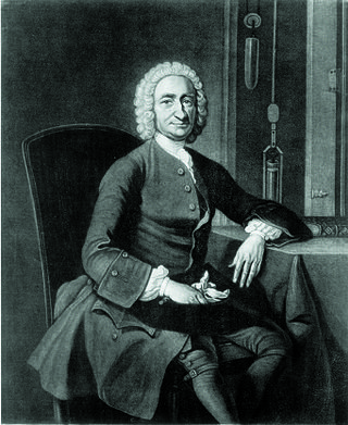
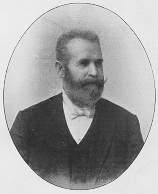
Sigmund Riefler was a German physicist, inventor and precision clockmaker.
The échappement naturel was the invention of Abraham-Louis Breguet, one of the most eminent watchmakers of all time. Following the introduction of the detent chronometer escapement with a temperature compensated balance, very close rates could be achieved in marine chronometers and to a lesser degree in pocket chronometers. This achievement was due, other things being equal, to the minimal interference with the balance during unlocking and impulse. A further key advantage of this escapement was that there was no need for oil on the escapement's working surfaces and hence no deterioration in the friction between the working surfaces as the oil aged. A drawback was that the detent escapement as it was used in pocket chronometers was prone to stopping as a result of motion. Most escapements are capable of being stopped by a sudden movement but the detent escapement gives an impulse to the balance only when it is moving in one direction. The escapement is therefore not self-starting. The lever escapement, as used in most modern mechanical watches, avoided this problem. In common with most other escapements it gave an impulse to the balance in both directions of the balance swing. This creates another problem in doing so because the introduction of a lever between the balance and the final (escape) wheel of the escapement requires lubrication on the acting surfaces.
William Hamilton Shortt (1881-1971) was a railway engineer and noted horologist, responsible for the design of the Shortt-Synchronome free pendulum clock, a widely used time standard, employed internationally in observatories in the period between the two World Wars. His deep involvement in precision timekeeping, as a colleague of Frank Hope-Jones and director of the Synchronome Company, derived from work on the safety of train travel and the accurate measurement of train speeds, following investigations into a serious train derailment of a LSWR train at Salisbury Station in 1906, when twenty-eight people died.
This page is based on this Wikipedia article Text is available under the CC BY-SA 4.0 license; additional terms may apply. Images, videos and audio are available under their respective licenses.