Ring oscillator test structures fabricated on silicon using p-type MOSFETs of different sizes. A schematic of a simple 3-inverter ring oscillator whose output frequency is 1/(6×inverter delay).
A ring oscillator is a device composed of an odd number of NOT gates in a ring, whose output oscillates between two voltage levels, representing true and false. The NOT gates, or inverters, are attached in a chain and the output of the last inverter is fed back into the first.
Because a single inverter computes the logical NOT of its input, it can be shown that the last output of a chain of an odd number of inverters is the logical NOT of the first input. The final output is asserted a finite amount of time after the first input is asserted and the feedback of the last output to the input causes oscillation.
A circular chain composed of an even number of inverters cannot be used as a ring oscillator. The last output in this case is the same as the input. However, this configuration of inverter feedback can be used as a storage element and it is the basic building block of static random access memory or SRAM.
The stages of the ring oscillator are often differential stages, that are more immune to external disturbances. This renders available also non-inverting stages. A ring oscillator can be made with a mix of inverting and non-inverting stages, provided the total number of inverting stages is odd. The oscillator period is in all cases equal to twice the sum of the individual delays of all stages.
A ring oscillator only requires power to operate. Above a certain voltage, typical well below the threshold voltage of the MOSFETs used, oscillations begin spontaneously. To increase the frequency of oscillation, two methods are commonly used. First, making the ring from a smaller number of inverters results in a higher frequency of oscillation, with about the same power consumption. Second, the supply voltage may be increased. In circuits where this method can be applied, it reduces the propagation delay through the chain of stages, increasing both the frequency of the oscillation and the current consumed.
Operation
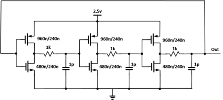
A transistor level schematic of a three-stage ring oscillator with delay in a .25u CMOS process. This particular circuit has high power consumption for its speed, since the inverters run a large current from power to ground when their inputs are at an intermediate voltage. A circuit with current-limiting devices in series with the inverter switches is more energy efficient.
To understand the operation of a ring oscillator, one must first understand gate delay. In a physical device, no gate can switch instantaneously. In a device fabricated with MOSFETs, for example, the gate capacitance must be charged before current can flow between the source and the drain. Thus, the output of every inverter in a ring oscillator changes within a finite amount of time after the input has changed. From here, it can be easily seen that adding more inverters to the chain increases the total gate delay, reducing the frequency of oscillation.
The ring oscillator is a member of the class of time-delay oscillators. A time-delay oscillator consists of an inverting amplifier with a delay element between the amplifier output and its input. The amplifier must have a gain greater than 1 at the intended oscillation frequency. Consider the initial case where the amplifier input and output voltages are momentarily balanced at a stable point. A small amount of noise can cause the amplifier output to rise slightly. After passing through the time-delay element, this small output voltage change will be presented to the amplifier input. The amplifier has a negative gain of greater than 1, so the output will change in the direction opposite to this input voltage. It will change by an amount larger than the input value, for a gain greater than 1. This amplified and reversed signal propagates from the output through the time-delay and back to the input where it is amplified and inverted again. The result of this sequential loop is a square-wave signal at the amplifier output with the period of each half of the square wave equal to the time delay. The square wave will grow until the amplifier output voltage reaches its limits, where it will stabilize. A more exact analysis will show that the wave that grows from the initial noise may not be square as it grows, but it will become square as the amplifier reaches its output limits.
The ring oscillator is a distributed version of the time-delay oscillator. The ring oscillator uses an odd number of inverters to give the effect of a single inverting amplifier with a gain of greater than one (Although, a single inverter in a loop is stable and a ring oscillator with odd number or inverters in a loop, is not). Rather than having a single delay element, each inverter contributes to the delay of the signal around the ring of inverters, hence the name ring oscillator. Adding pairs of inverters to the ring increases the total delay and thereby decreases the oscillator frequency. Changing the supply voltage changes the delay through each inverter, with higher voltages typically decreasing the delay and increasing the oscillator frequency. Vratislav describes some methods of frequency-stability and power consumption improving of the CMOS ring-oscillator.[1]
If t represents the time delay for a single inverter and n represents the number of inverters in the inverter chain, then the frequency of oscillation is given by:
The period of a ring oscillator varies in a random manner as T+T' where T' is a random value. In high-quality circuits, the range of T' is relatively small compared to the average period T. This variation in oscillator period is called jitter.[3]
Local temperature effects cause the period of a ring oscillator to wander above and below the long-term average period.[4] When the local silicon is cold, the propagation delay is slightly shorter, causing the ring oscillator to run at a slightly higher frequency, which eventually raises the local temperature. When the local silicon is hot, the propagation delay is slightly longer, causing the ring oscillator to run at a slightly lower frequency, which eventually lowers the local temperature. So, the frequency of a silicon ring oscillator will generally be stable, when the ambient temperature is constant and factors of heat transfer from the device to the ambient environment do not vary.
A ring oscillator is sometimes used to demonstrate a new hardware technology, analogous to the way a hello world program is often used to demonstrate a new software technology.[7][8]
Many wafers include a ring oscillator as part of the scribe line test structures. They are used during wafer testing to measure the effects of manufacturing process variations.[9]
Ring oscillators can also be used to measure the effects of voltage and temperature on a chip.[10]
An electronic oscillator is an electronic circuit that produces a periodic, oscillating or alternating current (AC) signal, usually a sine wave, square wave or a triangle wave, powered by a direct current (DC) source. Oscillators are found in many electronic devices, such as radio receivers, television sets, radio and television broadcast transmitters, computers, computer peripherals, cellphones, radar, and many other devices.
An amplifier, electronic amplifier or (informally) amp is an electronic device that can increase the magnitude of a signal. It is a two-port electronic circuit that uses electric power from a power supply to increase the amplitude of a signal applied to its input terminals, producing a proportionally greater amplitude signal at its output. The amount of amplification provided by an amplifier is measured by its gain: the ratio of output voltage, current, or power to input. An amplifier is defined as a circuit that has a power gain greater than one.
An operational amplifier is a DC-coupled electronic voltage amplifier with a differential input, a (usually) single-ended output, and an extremely high gain. Its name comes from its original use of performing mathematical operations in analog computers.
In electronics, a comparator is a device that compares two voltages or currents and outputs a digital signal indicating which is larger. It has two analog input terminals and and one binary digital output . The output is ideally
A phase-locked loop or phase lock loop (PLL) is a control system that generates an output signal whose phase is fixed relative to the phase of an input signal. Keeping the input and output phase in lockstep also implies keeping the input and output frequencies the same, thus a phase-locked loop can also track an input frequency. And by incorporating a frequency divider, a PLL can generate a stable frequency that is a multiple of the input frequency.
The Hartley oscillator is an electronic oscillator circuit in which the oscillation frequency is determined by a tuned circuit consisting of capacitors and inductors, that is, an LC oscillator. The circuit was invented in 1915 by American engineer Ralph Hartley. The distinguishing feature of the Hartley oscillator is that the tuned circuit consists of a single capacitor in parallel with two inductors in series, and the feedback signal needed for oscillation is taken from the center connection of the two inductors.
A variable frequency oscillator (VFO) in electronics is an oscillator whose frequency can be tuned over some range. It is a necessary component in any tunable radio transmitter and in receivers that works by the superheterodyne principle. The oscillator controls the frequency to which the apparatus is tuned.
A voltage-controlled oscillator (VCO) is an electronic oscillator whose oscillation frequency is controlled by a voltage input. The applied input voltage determines the instantaneous oscillation frequency. Consequently, a VCO can be used for frequency modulation (FM) or phase modulation (PM) by applying a modulating signal to the control input. A VCO is also an integral part of a phase-locked loop. VCOs are used in synthesizers to generate a waveform whose pitch can be adjusted by a voltage determined by a musical keyboard or other input.
A Colpitts oscillator, invented in 1918 by Canadian-American engineer Edwin H. Colpitts using vacuum tubes, is one of a number of designs for LC oscillators, electronic oscillators that use a combination of inductors (L) and capacitors (C) to produce an oscillation at a certain frequency. The distinguishing feature of the Colpitts oscillator is that the feedback for the active device is taken from a voltage divider made of two capacitors in series across the inductor.
Linear electronic oscillator circuits, which generate a sinusoidal output signal, are composed of an amplifier and a frequency selective element, a filter. A linear oscillator circuit which uses an RC network, a combination of resistors and capacitors, for its frequency selective part is called an RC oscillator.
In electronics, a frequency multiplier is an electronic circuit that generates an output signal and that output frequency is a harmonic (multiple) of its input frequency. Frequency multipliers consist of a nonlinear circuit that distorts the input signal and consequently generates harmonics of the input signal. A subsequent bandpass filter selects the desired harmonic frequency and removes the unwanted fundamental and other harmonics from the output.
A Wien bridge oscillator is a type of electronic oscillator that generates sine waves. It can generate a large range of frequencies. The oscillator is based on a bridge circuit originally developed by Max Wien in 1891 for the measurement of impedances. The bridge comprises four resistors and two capacitors. The oscillator can also be viewed as a positive gain amplifier combined with a bandpass filter that provides positive feedback. Automatic gain control, intentional non-linearity and incidental non-linearity limit the output amplitude in various implementations of the oscillator.
In electronics, a delay-locked loop (DLL) is a pseudo-digital circuit similar to a phase-locked loop (PLL), with the main difference being the absence of an internal voltage-controlled oscillator, replaced by a delay line.
The Pierce oscillator is a type of electronic oscillator particularly well-suited for use in piezoelectric crystal oscillator circuits. Named for its inventor, George W. Pierce (1872–1956), the Pierce oscillator is a derivative of the Colpitts oscillator. Virtually all digital IC clock oscillators are of Pierce type, as the circuit can be implemented using a minimum of components: a single digital inverter, one resistor, two capacitors, and the quartz crystal, which acts as a highly selective filter element. The low manufacturing cost of this circuit and the frequency stability of quartz crystals make it advantageous for many consumer electronics applications.
Distributed amplifiers are circuit designs that incorporate transmission line theory into traditional amplifier design to obtain a larger gain-bandwidth product than is realizable by conventional circuits.
The operational transconductance amplifier (OTA) is an amplifier that outputs a current proportional to its input voltage. Thus, it is a voltage controlled current source (VCCS). Three types of OTAs are single-input single-output, differential-input single-output, and differential-input differential-output, however this article focuses on differential-input single-output. There may be an additional input for a current to control the amplifier's transconductance.
In electronic amplifiers, the phase margin (PM) is the difference between the phase lag φ and -180°, for an amplifier's output signal at zero dB gain - i.e. unity gain, or that the output signal has the same amplitude as the input.
A fully differential amplifier (FDA) is a DC-coupled high-gain electronic voltage amplifier with differential inputs and differential outputs. In its ordinary usage, the output of the FDA is controlled by two feedback paths which, because of the amplifier's high gain, almost completely determine the output voltage for any given input.
A delay-line oscillator is a form of electronic oscillator that uses a delay line as its principal timing element.
Adaptive voltage scaling (AVS) is a closed-loop dynamic power minimization technique that adjusts the voltage supplied to a computer chip to match the chip's power needs during operation. Many computer chips, especially those in mobile devices or Internet of things devices are constrained by the power available and face varying workloads. In other situations a chip may be constrained by the amount of heat it is allowed to generate. In addition, individual chips can vary in their efficiency due to many factors, including minor differences in manufacturing conditions. AVS allows the voltage supplied to the chip, and therefore its power consumption, to be continuously adjusted to be appropriate to the workload and the parameters of the specific chip. This is accomplished by integrating a device that monitors the performance of the chip into the chip, which then provides information to a power controller.
This page is based on this Wikipedia article Text is available under the CC BY-SA 4.0 license; additional terms may apply. Images, videos and audio are available under their respective licenses.