Rotary phase converter

Last updated
A simple homemade phase converter Basic Phase Converter.jpg
A simple homemade phase converter

A rotary phase converter, abbreviated RPC, is an electrical machine that converts power from one polyphase system to another, converting through rotary motion. Typically, single-phase electric power is used to produce three-phase electric power locally to run three-phase loads in premises where only single-phase is available.

Contents

Operation

A basic three-phase induction motor will have three windings, each end connected to terminals typically numbered (arbitrarily) as L1, L2, and L3 and sometimes T1, T2, T3.

A three-phase induction motor can be run at two-thirds of its rated horsepower on single-phase power applied to a single winding, once spun up by some means. A three-phase motor running on a single phase cannot start itself because it lacks the other phases to create a rotation on its own, much like a crank that is at dead center.

A three-phase induction motor that is spinning under single-phase power applied to terminals L1 and L2 will generate an electric potential (voltage) across terminal L3 in respect with L1 and L2. However, L1 to L3 and L2 to L3 will be 120 degrees out of phase with the input voltage, thus creating three-phase power. However, without current injection, special idler windings, or other means of regulation, the voltage will sag when a load is applied.

Power-factor correction is a very important consideration when building or choosing an RPC. This is desirable because an RPC that has power-factor correction will consume less current from the single-phase service supplying power to the phase converter and its loads.

A major concern with three phase power is that each phase be at similar voltages. A discrepancy between phases is known as phase imbalance. As a general guideline, unbalanced three-phase power that exceeds 4% in voltage variation can damage the equipment that it is meant to operate.

History

The first locomotive with a phase converter (only for demonstration purposes) V50.jpg
The first locomotive with a phase converter (only for demonstration purposes)
The Kando phase converter (1933) Kando-fele fazisvalto 1933-ban.jpg
The Kandó phase converter (1933)
The "Kando" locomotive, the first locomotive using a phase converter system Kando mozdony.jpg
The "Kandó" locomotive, the first locomotive using a phase converter system

At the beginning of the 20th century, there were two main principles of electric railway traction current systems:

  1. DC system
  2. 16⅔ Hz single phase system

These systems used series-wound traction motors. All of them needed a separated supply system or converters to take power from the standard 50 Hz electric network.

Kandó synchronous phase converter

Kálmán Kandó recognized that the electric traction system must be supplied by single-phase 50 Hz power from the standard electric network, and it must be converted in the locomotive to three-phase power for traction motors.

He created an electric machine called a synchronous phase converter, which was a single-phase synchronous motor and a three-phase synchronous generator with common stator and rotor.

It had two independent windings:

Single-phase supply

The direct feed from a standard electric network makes the system less complicated than the earlier systems and makes possible simple recuperation.

The single-phase feed makes it possible to use a single overhead line. More overhead lines increase the costs, and restrict the maximum speed of the trains.

Speed control

The asynchronous traction motor can run on a single RPM determined by the frequency of the feeding current and the loading torque.

The solution was to use more secondary windings on phase converter, and more windings on motor different number of magnetic poles.

Types

A rotary phase converter (RPC) may be built as a motor-generator set. These completely isolate the load from the single-phase supply and produce balanced three-phase output. However, due to weight, cost, and efficiency concerns, most RPCs are not built this way.

Instead, they are built out of a three-phase induction motor or generator, called an idler, on which two of the terminals (the idler inputs) are powered from the single-phase line. The rotating flux in the motor produces a voltage on the third terminal. A voltage is induced in the third terminal that is phase shifted from the voltage between the first two terminals. In a three-winding motor, two of the windings are acting as a motor, and the third winding is acting as a generator. Because two of the outputs are the same as the single phase input, their phase relationship is 180°[ citation needed ]. This leaves the synthesized phase to be +/-90° from the input terminals. This non-ideal phase relationship requires a slight power de-rating of motors driven by this type of phase converter. Also, since the third, synthesized phase is driven differently from the other two, its response to load changes may be different causing this phase to sag more under load. Since induction motors are sensitive to voltage imbalance, this is another factor in de-rating of motors driven by this type of phase converter. For example, a small 5% imbalance in phase voltage requires a much larger 24% reduction of motor rated power. [1] Thus tuning a rotary phase converter circuit for equal phase voltages under maximum load may be quite important.

Power quality

A common measure of the quality of the power produced by an RPC or any phase converter is the voltage balance, which may be measured while the RPC is driving a balanced load such as a three-phase motor. Other quality measures include the harmonic content of the power produced and the power factor of the RPC motor combination as seen by the utility. Selection of the best phase converter for any application depends on the sensitivity of the load to these factors. Three-phase induction motors are very sensitive to voltage imbalances.

The quality of three-phase power generated by such a phase converter depends upon a number of factors including:

Quality improvement

RPC manufacturers use a variety of techniques to deal with these problems. Some of the techniques include,

Uses

General

Demand exists for phase converters due to the use of three-phase motors. With increasing power output, three-phase motors have preferable characteristics to single-phase motors; the latter not being available in sizes over 15 hp (11 kW) and, though available, rarely seen larger than 5 hp (3.7 kW). (Three-phase motors have higher efficiency, reduced complexity, with regards to starting, and three-phase power is significantly available where they are used.)

Electric railways

Rotary phase converters are used to produce a single-phase for the single overhead conductor in electric railways.[ citation needed ] Five European countries (Germany, Austria, Switzerland, Norway, and Sweden), where electricity is three-phase AC at 50  Hz, have standardised on single-phase AC at 15 kV 16+23 Hz for railway electrification; phase converters are, therefore, used to change both phases and frequency. In the Soviet Union, they were used on AC locomotives to convert single phase, 50 Hz to 3-phase for driving induction motors for traction motor cooling blowers, etc. [2]

Alternatives to rotary converters

Alternatives exist to rotary phase converters for operation of three-phase equipment on a single-phase power supply.

Static phase converters

These may be an alternative where the issue at hand is starting a motor, rather than polyphase power itself. The static phase converter is used to start a three-phase motor. The motor then runs on a single phase with a synthesised third pole. However, this makes the power balance, and thus motor efficiency, extremely poor, requiring de-rating the motor (typically to 60% or less). Overheating, and quite often destruction of the motor, will result from failing to do so. (Many manufacturers and dealers specifically state that using a static converter will void any warranty.) An oversized static converter can remove the need to de-rate the motor, but at an increased cost.

Inverter drives (VFDs)

The popularity of the Variable-frequency drive (VFD) has increased in the last decade, especially in the home-shop market. This is because of their relative low cost and ability to generate three-phase output from single phase input. A VFD converts AC power to DC and then converts it back to AC through a transistor bridge, a technology that is somewhat analogous to that of a switch-mode power supply. As the VFD generates its AC output from the DC bus, it is possible to power a three-phase motor from a single-phase source. Nevertheless, commercial-grade VFDs are produced that require three-phase input, as there are some efficiency gains to be had with such an arrangement.

A typical VFD functions by rapidly switching transistors on and off to "chop" the voltage on the DC bus through what is known as pulse-width modulation (PWM). Proper use of PWM will result in an AC output whose voltage and frequency can be varied over a fairly wide range. As an induction motor's rotational speed is proportional to input frequency, a change in the VFD's output frequency will cause the motor to change speed. Voltage is also changed in a way that results in the motor producing a relatively constant torque over the useful speed range.

The output of a quality VFD is an approximation of a sine wave, with some high frequency harmonic content. Harmonic content will elevate motor temperature and may produce some whistling or whining noise that could be objectionable. The effects of unwanted harmonics can be mitigated by the use of reactive output filtering, which is incorporated into better quality VFDs. Reactive filtration impedes the high frequency harmonic content but has little effect on the fundamental frequency that determines motor speed. The result is an output to the motor that is closer to an ideal sine wave.

In the past, VFDs that have a capacity greater than 3 hp (2.2 kW) were costly, thus making the rotary phase converter (RPC) an attractive alternative. However, modern VFDs have dropped considerably in cost, making them more affordable than comparable RPCs. Also working in the VFD's favor is its more compact size relative to its electrical capacity. A plus is many VFDs can produce a "soft start" effect (in which power is gradually applied to the motor), which reduces the amount of current that must be delivered at machine start-up.

Use of a VFD may result in motor damage if the motor is not rated for such an application. This is primarily because most induction motors are forced-air cooled by a fan or blower driven by the motor itself. Operating such a motor at a lower-than-normal speed will substantially reduce the cooling airflow, increasing the likelihood of overheating and winding damage or failure, especially while operating at full load. A manufacturer may void the warranty on a motor powered by a VFD unless the motor is "inverter-rated." As VFDs are the most popular method of powering motors in new commercial installations, most three-phase motors sold today are, in fact, inverter-rated.

See also

Related Research Articles

<span class="mw-page-title-main">Rectifier</span> Electrical device that converts AC to DC

A rectifier is an electrical device that converts alternating current (AC), which periodically reverses direction, to direct current (DC), which flows in only one direction. The reverse operation is performed by an inverter.

<span class="mw-page-title-main">Electric motor</span> Machine that converts electrical energy into mechanical energy

An electric motor is an electrical machine that converts electrical energy into mechanical energy. Most electric motors operate through the interaction between the motor's magnetic field and electric current in a wire winding to generate force in the form of torque applied on the motor's shaft. An electric generator is mechanically identical to an electric motor, but operates with a reversed flow of power, converting mechanical energy into electrical energy.

<span class="mw-page-title-main">Alternator</span> Device converting mechanical into electrical energy

An alternator is an electrical generator that converts mechanical energy to electrical energy in the form of alternating current. For reasons of cost and simplicity, most alternators use a rotating magnetic field with a stationary armature. Occasionally, a linear alternator or a rotating armature with a stationary magnetic field is used. In principle, any AC electrical generator can be called an alternator, but usually the term refers to small rotating machines driven by automotive and other internal combustion engines.

<span class="mw-page-title-main">Power inverter</span> Device that changes direct current (DC) to alternating current (AC)

A power inverter, inverter or invertor is a power electronic device or circuitry that changes direct current (DC) to alternating current (AC). The resulting AC frequency obtained depends on the particular device employed. Inverters do the opposite of rectifiers which were originally large electromechanical devices converting AC to DC.

<span class="mw-page-title-main">Induction motor</span> Type of AC electric motor

An induction motor or asynchronous motor is an AC electric motor in which the electric current in the rotor needed to produce torque is obtained by electromagnetic induction from the magnetic field of the stator winding. An induction motor can therefore be made without electrical connections to the rotor. An induction motor's rotor can be either wound type or squirrel-cage type.

<span class="mw-page-title-main">Utility frequency</span> Frequency used on standard electricity grid in a given area

The utility frequency, (power) line frequency or mains frequency is the nominal frequency of the oscillations of alternating current (AC) in a wide area synchronous grid transmitted from a power station to the end-user. In large parts of the world this is 50 Hz, although in the Americas and parts of Asia it is typically 60 Hz. Current usage by country or region is given in the list of mains electricity by country.

<span class="mw-page-title-main">Traction motor</span> An electric motor for vehicle propulsion

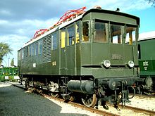
A traction motor is an electric motor used for propulsion of a vehicle, such as locomotives, electric or hydrogen vehicles, or electric multiple unit trains.

<span class="mw-page-title-main">Motor–generator</span> Device for converting electrical power to another form

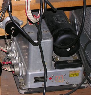
A motor–generator is a device for converting electrical power to another form. Motor–generator sets are used to convert frequency, voltage, or phase of power. They may also be used to isolate electrical loads from the electrical power supply line. Large motor–generators were widely used to convert industrial amounts of power while smaller motor–generators were used to convert battery power to higher DC voltages.

<span class="mw-page-title-main">Rotary converter</span>

A rotary converter is a type of electrical machine which acts as a mechanical rectifier, inverter or frequency converter.

<span class="mw-page-title-main">Traction substation</span>

A traction substation, traction current converter plant, rectifier station or traction power substation (TPSS) is an electrical substation that converts electric power from the form provided by the electrical power industry for public utility service to an appropriate voltage, current type and frequency to supply railways, trams (streetcars) or trolleybuses with traction current.

<span class="mw-page-title-main">15 kV AC railway electrification</span> Standard current and voltage settings for much of Central Europes train transport

Railway electrification using alternating current (AC) at 15 kilovolts (kV) and 16.7 hertz (Hz) are used on transport railways in Germany, Austria, Switzerland, Sweden, and Norway. The high voltage enables high power transmission with the lower frequency reducing the losses of the traction motors that were available at the beginning of the 20th century. Railway electrification in late 20th century tends to use 25 kV, 50 Hz AC systems which has become the preferred standard for new railway electrifications but extensions of the existing 15 kV networks are not completely unlikely. In particular, the Gotthard Base Tunnel still uses 15 kV, 16.7 Hz electrification.

<span class="mw-page-title-main">Variable-frequency drive</span> Type of adjustable-speed drive

A variable-frequency drive, variable-speed drives, AC drives, micro drives, inverter drives, or drives) is a type of AC motor drive that controls speed and torque by varying the frequency of the input electricity. Depending on its topology, it controls the associated voltage or current variation.

<span class="mw-page-title-main">Frequency changer</span>

A frequency changer or frequency converter is an electronic or electromechanical device that converts alternating current (AC) of one frequency to alternating current of another frequency. The device may also change the voltage, but if it does, that is incidental to its principal purpose, since voltage conversion of alternating current is much easier to achieve than frequency conversion.

<span class="mw-page-title-main">Cycloconverter</span> Electrical circuit that changes AC frequency

A cycloconverter (CCV) or a cycloinverter converts a constant amplitude, constant frequency AC waveform to another AC waveform of a lower frequency by synthesizing the output waveform from segments of the AC supply without an intermediate DC link. There are two main types of CCVs, circulating current type or blocking mode type, most commercial high power products being of the blocking mode type.

<span class="mw-page-title-main">Motor drive</span>

Motor drive means a system that includes a motor. An adjustable speed motor drive means a system that includes a motor that has multiple operating speeds. A variable speed motor drive is a system that includes a motor and is continuously variable in speed. If the motor is generating electrical energy rather than using it – this could be called a generator drive but is often still referred to as a motor drive.

<span class="mw-page-title-main">Phase converter</span>

A phase converter is a device that converts electric power provided as single phase to multiple phase or vice versa. The majority of phase converters are used to produce three-phase electric power from a single-phase source, thus allowing the operation of three-phase equipment at a site that only has single-phase electrical service. Phase converters are used where three-phase service is not available from the utility provider or is too costly to install. A utility provider will generally charge a higher fee for a three-phase service because of the extra equipment, including transformers, metering, and distribution wire required to complete a functional installation.

<span class="mw-page-title-main">AC motor</span> Electric motor driven by an AC electrical input

An AC motor is an electric motor driven by an alternating current (AC). The AC motor commonly consists of two basic parts, an outside stator having coils supplied with alternating current to produce a rotating magnetic field, and an inside rotor attached to the output shaft producing a second rotating magnetic field. The rotor magnetic field may be produced by permanent magnets, reluctance saliency, or DC or AC electrical windings.

Doubly fed electric machines, also slip-ring generators, are electric motors or electric generators, where both the field magnet windings and armature windings are separately connected to equipment outside the machine.

<span class="mw-page-title-main">Amtrak's 25 Hz traction power system</span> Unique electrical supply on the NEC

Amtrak's 25 Hz traction power system is a traction power grid operated by Amtrak along the southern portion of its Northeast Corridor (NEC): the 226.6 route miles (362 km) between Washington, D.C. and New York City and the 104 route miles (167 km) between Philadelphia and Harrisburg, Pennsylvania. The Pennsylvania Railroad constructed it between 1915 and 1938. Amtrak inherited the system from Penn Central, the successor to the Pennsylvania Railroad, in 1976, along with the Northeast Corridor. This is the reason for using 25 Hz, as opposed to 60 Hz, which is the standard for power transmission in North America. In addition to serving the NEC, the system provides power to NJ Transit Rail Operations (NJT), the Southeastern Pennsylvania Transportation Authority (SEPTA) and the Maryland Area Regional Commuter Train (MARC). Only about half of the system's electrical capacity is used by Amtrak. The remainder is sold to the commuter railroads who operate their trains along the corridor.

This glossary of electrical and electronics engineering is a list of definitions of terms and concepts related specifically to electrical engineering and electronics engineering. For terms related to engineering in general, see Glossary of engineering.

References

  1. "Voltage Imbalance - Derating Factor in Polyphase Motors". engineeringtoolbox.com. The Engineering Toolbox. Retrieved 17 November 2019.
  2. Захарченко Д.Д., Ротанов Н.А. "Тяговые электрические машины" (Traction electrical мachinery) Москва, Транспорт, 1991 - 343 p., p.231