Shell-and-tube heat exchanger

Last updated
Fluid flow simulation for a shell-and-tube style exchanger; The shell inlet is at the top rear and outlet in the foreground at the bottom Shell tube flow.png
Fluid flow simulation for a shell-and-tube style exchanger; The shell inlet is at the top rear and outlet in the foreground at the bottom
Shell and tube heat exchanger Shell and tube heat exchanger.jpg
Shell and tube heat exchanger

A shell-and-tube heat exchanger is a class of heat exchanger designs. [1] [2] It is the most common type of heat exchanger in oil refineries and other large chemical processes, and is suited for higher-pressure applications. As its name implies, this type of heat exchanger consists of a shell (a large pressure vessel) with a bundle of tubes inside it. One fluid runs through the tubes, and another fluid flows over the tubes (through the shell) to transfer heat between the two fluids. The set of tubes is called a tube bundle, and may be composed of several types of tubes: plain, longitudinally finned, etc.

Contents

Theory and application

Two fluids, of different starting temperatures, flow through the heat exchanger. One flows through the tubes (the tube side) and the other flows outside the tubes but inside the shell (the shell side). Heat is transferred from one fluid to the other through the tube walls, either from tube side to shell side or vice versa. The fluids can be either liquids or gases on either the shell or the tube side. In order to transfer heat efficiently, a large heat transfer area should be used, leading to the use of many tubes. In this way, waste heat can be put to use. This is an efficient way to conserve energy.

Heat exchangers with only one phase (liquid or gas) on each side can be called one-phase or single-phase heat exchangers. Two-phase heat exchangers can be used to heat a liquid to boil it into a gas (vapor), sometimes called boilers, or to cool the vapors and condense it into a liquid (called condensers), with the phase change usually occurring on the shell side. Boilers in steam engine locomotives are typically large, usually cylindrically-shaped shell-and-tube heat exchangers. In large power plants with steam-driven turbines, shell-and-tube surface condensers are used to condense the exhaust steam exiting the turbine into condensate water which is recycled back to be turned into steam in the steam generator.

They are also used in liquid-cooled chillers for transferring heat between the refrigerant and the water in both the evaporator and condenser, and in air-cooled chillers for only the evaporator.

Shell and tube heat exchanger design

There can be many variations on the shell-and tube-design. Typically, the ends of each tube are connected to plenums (sometimes called water boxes) through holes in tubesheets. The tubes may be straight or bent in the shape of a U, called U-tubes.

U-tube heat exchanger.svg

In nuclear power plants called pressurized water reactors, large heat exchangers called steam generators are two-phase, shell-and-tube heat exchangers which typically have U-tubes. They are used to boil water recycled from a surface condenser into steam to drive a turbine to produce power. Most shell-and-tube heat exchangers are either 1, 2, or 4 pass designs on the tube side. This refers to the number of times the fluid in the tubes passes through the fluid in the shell. In a single pass heat exchanger, the fluid goes in one end of each tube and out the other.

Straight-tube heat exchanger 1-pass.svg

Surface condensers in power plants are often 1-pass straight-tube heat exchangers (see surface condenser for diagram). Two and four pass designs are common because the fluid can enter and exit on the same side. This makes construction much simpler.

Straight-tube heat exchanger 2-pass.svg

There are often baffles directing flow through the shell side so the fluid does not take a short cut through the shell side leaving ineffective low flow volumes. These are generally attached to the tube bundle rather than the shell in order that the bundle is still removable for maintenance.

Countercurrent heat exchangers are most efficient because they allow the highest log mean temperature difference between the hot and cold streams. Many companies however do not use two pass heat exchangers with a u-tube because they can break easily in addition to being more expensive to build. Often multiple heat exchangers can be used to simulate the countercurrent flow of a single large exchanger.

Selection of tube material

Tube bundle of a shell & tube heat exchanger (before assembly).jpg
Tube bundle of a shell & tube heat exchanger (before assembly) - 2.jpg
Tube bundle shell and tube heat exchanger.jpg
Examples for tube bundles of shell-and-tube heat exchangers

To be able to transfer heat well, the tube material should have good thermal conductivity. Because heat is transferred from a hot to a cold side through the tubes, there is a temperature difference through the width of the tubes. Because of the tendency of the tube material to thermally expand differently at various temperatures, thermal stresses occur during operation. This is in addition to any stress from high pressures from the fluids themselves. The tube material also should be compatible with both the shell-and-tube side fluids for long periods under the operating conditions (temperatures, pressures, pH, etc.) to minimize deterioration such as corrosion. All of these requirements call for careful selection of strong, thermally-conductive, corrosion-resistant, high quality tube materials, typically metals, including aluminium, copper alloy, stainless steel, carbon steel, non-ferrous copper alloy, Inconel, nickel, Hastelloy and titanium. [3] Fluoropolymers such as Perfluoroalkoxy alkane (PFA) and Fluorinated ethylene propylene (FEP) are also used to produce the tubing material due to their high resistance to extreme temperatures. [4] Poor choice of tube material could result in a leak through a tube between the shell-and-tube sides causing fluid cross-contamination and possibly loss of pressure.

Applications and uses

The simple design of a shell-and-tube heat exchanger makes it an ideal cooling solution for a wide variety of applications. One of the most common applications is the cooling of hydraulic fluid and oil in engines, transmissions and hydraulic power packs. With the right choice of materials they can also be used to cool or heat other mediums, such as swimming pool water or charge air. [5] There are many advantages to shell-and-tube technology over plates

Overpressure protection

In shell-and-tube heat exchangers there is a potential for a tube to rupture and for high pressure (HP) fluid to enter and over-pressurise the low pressure (LP) side of the heat exchanger. [7] The usual configuration of exchangers is for the HP fluid to be in the tubes and for LP water, cooling or heating media to be on the shell side. There is a risk that a tube rupture could compromise the integrity of the shell and the release flammable gas or liquid, with a risk to people and financial loss. The shell of an exchanger must be protected against over-pressure by rupture discs or relief valves. The opening time of protection devices has been found to be critical for exchanger protection. [8] Such devices are fitted directly on the shell of the exchanger and discharge into a relief system.

Tubes

Overview

Shell-and-tube heat exchangers are integral components in thermal engineering, primarily used for efficient heat transfer. The design and arrangement of the tubes within these exchangers are fundamental to their operation and effectiveness. [9] The precise design and specification of tubes in shell and tube heat exchangers underscore the complexities of thermal engineering. Each design aspect, from material selection to tube arrangement and fluid flow, plays a vital role in the exchanger's performance, showcasing the intricacies and precision required in this field. [9]

Specification and Standards

Tubes in these exchangers, often termed as condenser tubes, are distinct from typical water tubing. They adhere to the Birmingham Wire Gage (BWG) standard, which dictates specific dimensions such as the outside diameter. For example, a 1-inch tube according to BWG will have an exact outside diameter of 1 inch. [10] Detailed specifications are available in specialized references.

Materials

The tubes are made from a variety of materials, each chosen based on specific system requirements including thermal conductivity, strength, and corrosion resistance. [9]

Tube Arrangement

The arrangement of tubes is a crucial design aspect. They are positioned in holes drilled in tube sheets, with the spacing between holes - known as tube pitch - being a key factor for both structural integrity and efficiency. [9] Tubes are typically organized in square or triangular patterns, and specific layouts are detailed in engineering references.

Tube Counts

Tube count refers to the maximum number of tubes that can fit within a shell of a specific diameter without weakening the tube sheet. [9] This aspect is crucial for ensuring the structural integrity and efficiency of the heat exchanger. Information on tube counts for various shell sizes can be found in specialized literature.

Fluid Flow

In shell and tube heat exchangers, there are two distinct fluid streams for heat transfer. The tube fluid circulates inside the tubes, while the shell fluid flows around them, guided by baffles. The movement of the shell fluid, whether it is side-to-side or up-and-down, and the number of passes it makes over the tubes, are controlled by segmental baffles, essential for maximizing heat transfer efficiency. [9] These aspects are elaborated in dedicated references.

Design and construction standards

See also

Related Research Articles

<span class="mw-page-title-main">Pressurized water reactor</span> Type of nuclear reactor

A pressurized water reactor (PWR) is a type of light-water nuclear reactor. PWRs constitute the large majority of the world's nuclear power plants. In a PWR, the primary coolant (water) is pumped under high pressure to the reactor core where it is heated by the energy released by the fission of atoms. The heated, high pressure water then flows to a steam generator, where it transfers its thermal energy to lower pressure water of a secondary system where steam is generated. The steam then drives turbines, which spin an electric generator. In contrast to a boiling water reactor (BWR), pressure in the primary coolant loop prevents the water from boiling within the reactor. All light-water reactors use ordinary water as both coolant and neutron moderator. Most use anywhere from two to four vertically mounted steam generators; VVER reactors use horizontal steam generators.

<span class="mw-page-title-main">Heat exchanger</span> Equipment used to transfer heat between fluids

A heat exchanger is a system used to transfer heat between a source and a working fluid. Heat exchangers are used in both cooling and heating processes. The fluids may be separated by a solid wall to prevent mixing or they may be in direct contact. They are widely used in space heating, refrigeration, air conditioning, power stations, chemical plants, petrochemical plants, petroleum refineries, natural-gas processing, and sewage treatment. The classic example of a heat exchanger is found in an internal combustion engine in which a circulating fluid known as engine coolant flows through radiator coils and air flows past the coils, which cools the coolant and heats the incoming air. Another example is the heat sink, which is a passive heat exchanger that transfers the heat generated by an electronic or a mechanical device to a fluid medium, often air or a liquid coolant.

<span class="mw-page-title-main">Boiler</span> Closed vessel in which fluid is heated

A boiler is a closed vessel in which fluid is heated. The fluid does not necessarily boil. The heated or vaporized fluid exits the boiler for use in various processes or heating applications, including water heating, central heating, boiler-based power generation, cooking, and sanitation.
<span class="mw-page-title-main">Heat pipe</span> Heat-transfer device that employs phase transition

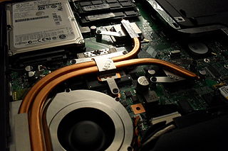
A heat pipe is a heat-transfer device that employs phase transition to transfer heat between two solid interfaces.

<span class="mw-page-title-main">Rankine cycle</span> Model that is used to predict the performance of steam turbine systems

The Rankine cycle is an idealized thermodynamic cycle describing the process by which certain heat engines, such as steam turbines or reciprocating steam engines, allow mechanical work to be extracted from a fluid as it moves between a heat source and heat sink. The Rankine cycle is named after William John Macquorn Rankine, a Scottish polymath professor at Glasgow University.

<span class="mw-page-title-main">Chiller</span> Machine that removes heat from a liquid coolant via vapor compression

A chiller is a machine that removes heat from a liquid coolant via a vapor-compression, adsorption refrigeration, or absorption refrigeration cycles. This liquid can then be circulated through a heat exchanger to cool equipment, or another process stream. As a necessary by-product, refrigeration creates waste heat that must be exhausted to ambience, or for greater efficiency, recovered for heating purposes. Vapor compression chillers may use any of a number of different types of compressors. Most common today are the hermetic scroll, semi-hermetic screw, or centrifugal compressors. The condensing side of the chiller can be either air or water cooled. Even when liquid cooled, the chiller is often cooled by an induced or forced draft cooling tower. Absorption and adsorption chillers require a heat source to function.

<span class="mw-page-title-main">Thermal power station</span> Power plant that generates electricity from heat energy

A thermal power station is a type of power station in which heat energy is converted to electrical energy. In a steam-generating cycle heat is used to boil water in a large pressure vessel to produce high-pressure steam, which drives a steam turbine connected to an electrical generator. The low-pressure exhaust from the turbine enters a steam condenser where it is cooled to produce hot condensate which is recycled to the heating process to generate more high pressure steam. This is known as a Rankine cycle.

<span class="mw-page-title-main">Surface condenser</span> Steam engine component

A surface condenser is a water-cooled shell and tube heat exchanger installed to condense exhaust steam from a steam turbine in thermal power stations. These condensers are heat exchangers which convert steam from its gaseous to its liquid state at a pressure below atmospheric pressure. Where cooling water is in short supply, an air-cooled condenser is often used. An air-cooled condenser is however, significantly more expensive and cannot achieve as low a steam turbine exhaust pressure as a water-cooled surface condenser.

<span class="mw-page-title-main">Absorption refrigerator</span> Refrigerator that uses a heat source

An absorption refrigerator is a refrigerator that uses a heat source to provide the energy needed to drive the cooling process. Solar energy, burning a fossil fuel, waste heat from factories, and district heating systems are examples of convenient heat sources that can be used. An absorption refrigerator uses two coolants: the first coolant performs evaporative cooling and then is absorbed into the second coolant; heat is needed to reset the two coolants to their initial states. Absorption refrigerators are commonly used in recreational vehicles (RVs), campers, and caravans because the heat required to power them can be provided by a propane fuel burner, by a low-voltage DC electric heater or by a mains-powered electric heater. Absorption refrigerators can also be used to air-condition buildings using the waste heat from a gas turbine or water heater in the building. Using waste heat from a gas turbine makes the turbine very efficient because it first produces electricity, then hot water, and finally, air-conditioning—trigeneration.

<span class="mw-page-title-main">Steam-electric power station</span>

The steam-electric power station is a power station in which the electric generator is steam driven. Water is heated, turns into steam and spins a steam turbine which drives an electrical generator. After it passes through the turbine, the steam is condensed in a condenser. The greatest variation in the design of steam-electric power plants is due to the different fuel sources.

Economizers, or economisers (UK), are mechanical devices intended to reduce energy consumption, or to perform useful function such as preheating a fluid. The term economizer is used for other purposes as well. Boiler, power plant, heating, refrigeration, ventilating, and air conditioning (HVAC) uses are discussed in this article. In simple terms, an economizer is a heat exchanger.

<span class="mw-page-title-main">Marine heat exchanger</span>

Marine heat exchangers are no different than non-marine heat exchangers except for the simple fact that they are found aboard ships. Heat exchangers can be used for a wide variety of uses. As the name implies, these can be used for heating as well as cooling. The two primary types of marine heat exchangers used aboard vessels in the maritime industry are plate, and shell and tube. Maintenance for heat exchangers prevents fouling and galvanic corrosion from dissimilar metals.

<span class="mw-page-title-main">Evaporator</span> Machine transforming a liquid into a gas

An evaporator is a type of heat exchanger device that facilitates evaporation by utilizing conductive and convective heat transfer, which provides the necessary thermal energy for phase transition from liquid to vapor. Within evaporators, a circulating liquid is exposed to an atmospheric or reduced pressure environment, causing it to boil at a lower temperature compared to normal atmospheric boiling.

A regenerative heat exchanger, or more commonly a regenerator, is a type of heat exchanger where heat from the hot fluid is intermittently stored in a thermal storage medium before it is transferred to the cold fluid. To accomplish this the hot fluid is brought into contact with the heat storage medium, then the fluid is displaced with the cold fluid, which absorbs the heat.

<span class="mw-page-title-main">Boiler (power generation)</span> High pressure steam generator

A boiler or steam generator is a device used to create steam by applying heat energy to water. Although the definitions are somewhat flexible, it can be said that older steam generators were commonly termed boilers and worked at low to medium pressure but, at pressures above this, it is more usual to speak of a steam generator.
<span class="mw-page-title-main">Condenser (heat transfer)</span> System for condensing gas into liquid by cooling

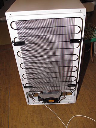
In systems involving heat transfer, a condenser is a heat exchanger used to condense a gaseous substance into a liquid state through cooling. In so doing, the latent heat is released by the substance and transferred to the surrounding environment. Condensers are used for efficient heat rejection in many industrial systems. Condensers can be made according to numerous designs and come in many sizes ranging from rather small (hand-held) to very large. For example, a refrigerator uses a condenser to get rid of heat extracted from the interior of the unit to the outside air.

HVAC is a major sub discipline of mechanical engineering. The goal of HVAC design is to balance indoor environmental comfort with other factors such as installation cost, ease of maintenance, and energy efficiency. The discipline of HVAC includes a large number of specialized terms and acronyms, many of which are summarized in this glossary.

<span class="mw-page-title-main">Hygroscopic cycle</span> Thermodynamic cycle converting thermal energy into mechanical power

The Hygroscopic cycle is a thermodynamic cycle converting thermal energy into mechanical power by the means of a steam turbine. It is similar to the Rankine cycle using water as the motive fluid but with the novelty of introducing salts and their hygroscopic properties for the condensation. The salts are desorbed in the boiler or steam generator, where clean steam is released and superheated in order to be expanded and generate power through the steam turbine. Boiler blowdown with the concentrated hygroscopic compounds is used thermally to pre-heat the steam turbine condensate, and as reflux in the steam-absorber.

A rising film or vertical long tube evaporator is a type of evaporator that is essentially a vertical shell and tube heat exchanger. The liquid being evaporated is fed from the bottom into long tubes and heated with steam condensing on the outside of the tube from the shell side. This is to produce steam and vapour within the tube bringing the liquid inside to a boil. The vapour produced then presses the liquid against the walls of the tubes and causes the ascending force of this liquid. As more vapour is formed, the centre of the tube will have a higher velocity which forces the remaining liquid against the tube wall forming a thin film which moves upwards. This phenomenon of the rising film gives the evaporator its name.

The low-temperature distillation (LTD) technology is the first implementation of the direct spray distillation (DSD) process. The first large-scale units are now in operation for desalination. The process was first developed by scientists at the University of Applied Sciences in Switzerland, focusing on low-temperature distillation in vacuum conditions, from 2000 to 2005.

References

  1. Sadik Kakaç & Hongtan Liu (2002). Heat Exchangers: Selection, Rating and Thermal Design (2nd ed.). CRC Press. ISBN   0-8493-0902-6.
  2. Perry, Robert H. & Green, Don W. (1984). Perry's Chemical Engineers' Handbook (6th ed.). McGraw-Hill. ISBN   0-07-049479-7.
  3. "Shell and Tube Exchangers" . Retrieved 2009-05-08.
  4. "PFA Properties" (PDF). www.fluorotherm.com/. Fluorotherm Polymers, Inc. Retrieved 4 November 2014.
  5. "Applications and Uses" . Retrieved 2016-01-25.
  6. Heat Exchanger Shell Bellows Archived 2018-10-05 at the Wayback Machine Piping Technology and Products, (retrieved March 2012)
  7. The Energy Institute (2015). Guidelines for the safe design and operation of shell-and-tube heat exchangers to withstand the impact of tube failure. London: The Energy Institute.
  8. The Institution of Chemical Engineers (21 March 2018). "Screening Heat Exchangers for High Pressure Differential Relief". The Institution of Chemical Engineers. Retrieved 24 January 2021.
  9. 1 2 3 4 5 6 Janna, William S. "Design of Fluid Thermal Systems," 4th edition. ISBN 9781285859651.
  10. Kern, D. Q. "Process Heat Transfer," McGraw-Hill Book Co., 1950, p. 843.