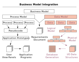
A data model is an abstract model that organizes elements of data and standardizes how they relate to one another and to the properties of real-world entities. For instance, a data model may specify that the data element representing a car be composed of a number of other elements which, in turn, represent the color and size of the car and define its owner.
In software and systems engineering, the phrase use case is a polyseme with two senses:
- A usage scenario for a piece of software; often used in the plural to suggest situations where a piece of software may be useful.
- A potential scenario in which a system receives an external request and responds to it.
A modeling language is any artificial language that can be used to express information or knowledge or systems in a structure that is defined by a consistent set of rules. The rules are used for interpretation of the meaning of components in the structure Programing language.

In systems engineering and software engineering, requirements analysis focuses on the tasks that determine the needs or conditions to meet the new or altered product or project, taking account of the possibly conflicting requirements of the various stakeholders, analyzing, documenting, validating and managing software or system requirements.

In systems engineering, information systems and software engineering, the systems development life cycle (SDLC), also referred to as the application development life cycle, is a process for planning, creating, testing, and deploying an information system. The SDLC concept applies to a range of hardware and software configurations, as a system can be composed of hardware only, software only, or a combination of both. There are usually six stages in this cycle: requirement analysis, design, development and testing, implementation, documentation, and evaluation.

Data modeling in software engineering is the process of creating a data model for an information system by applying certain formal techniques.

An information model in software engineering is a representation of concepts and the relationships, constraints, rules, and operations to specify data semantics for a chosen domain of discourse. Typically it specifies relations between kinds of things, but may also include relations with individual things. It can provide sharable, stable, and organized structure of information requirements or knowledge for the domain context.

The Department of Defense Architecture Framework (DoDAF) is an architecture framework for the United States Department of Defense (DoD) that provides visualization infrastructure for specific stakeholders concerns through viewpoints organized by various views. These views are artifacts for visualizing, understanding, and assimilating the broad scope and complexities of an architecture description through tabular, structural, behavioral, ontological, pictorial, temporal, graphical, probabilistic, or alternative conceptual means. The current release is DoDAF 2.02.

IDEF0, a compound acronym, is a function modeling methodology for describing manufacturing functions, which offers a functional modeling language for the analysis, development, reengineering and integration of information systems, business processes or software engineering analysis.
A conceptual model is a representation of a system. It consists of concepts used to help people know, understand, or simulate a subject the model represents. In contrast, a physical model focuses on a physical object such as a toy model that may be assembled and made to work like the object it represents.
Integration DEFinition for information modeling (IDEF1X) is a data modeling language for the development of semantic data models. IDEF1X is used to produce a graphical information model which represents the structure and semantics of information within an environment or system.

Unicom System Architect is an enterprise architecture tool that is used by the business and technology departments of corporations and government agencies to model their business operations and the systems, applications, and databases that support them. System Architect is used to build architectures using various frameworks including TOGAF, ArchiMate, DoDAF, MODAF, NAF and standard method notations such as sysML, UML, BPMN, and relational data modeling. System Architect is developed by UNICOM Systems, a division of UNICOM Global, a United States-based company.
Object-oriented design (OOD) is the process of planning a system of interacting objects for the purpose of solving a software problem. It is one approach to software design.

Enterprise modelling is the abstract representation, description and definition of the structure, processes, information and resources of an identifiable business, government body, or other large organization.

In software engineering, structured analysis (SA) and structured design (SD) are methods for analyzing business requirements and developing specifications for converting practices into computer programs, hardware configurations, and related manual procedures.

Misuse case is a business process modeling tool used in the software development industry. The term Misuse Case or mis-use case is derived from and is the inverse of use case. The term was first used in the 1990s by Guttorm Sindre of the Norwegian University of Science and Technology, and Andreas L. Opdahl of the University of Bergen, Norway. It describes the process of executing a malicious act against a system, while use case can be used to describe any action taken by the system.

ArchiMate is an open and independent enterprise architecture modeling language to support the description, analysis and visualization of architecture within and across business domains in an unambiguous way.
In systems engineering, software engineering, and computer science, a function model or functional model is a structured representation of the functions within the modeled system or subject area.

Semantic data model (SDM) is a high-level semantics-based database description and structuring formalism (database model) for databases. This database model is designed to capture more of the meaning of an application environment than is possible with contemporary database models. An SDM specification describes a database in terms of the kinds of entities that exist in the application environment, the classifications and groupings of those entities, and the structural interconnections among them. SDM provides a collection of high-level modeling primitives to capture the semantics of an application environment. By accommodating derived information in a database structural specification, SDM allows the same information to be viewed in several ways; this makes it possible to directly accommodate the variety of needs and processing requirements typically present in database applications. The design of the present SDM is based on our experience in using a preliminary version of it. SDM is designed to enhance the effectiveness and usability of database systems. An SDM database description can serve as a formal specification and documentation tool for a database; it can provide a basis for supporting a variety of powerful user interface facilities, it can serve as a conceptual database model in the database design process; and, it can be used as the database model for a new kind of database management system.

IDEF4, or Integrated DEFinition for Object-Oriented Design, is an object-oriented design modeling language for the design of component-based client/server systems. It has been designed to support smooth transition from the application domain and requirements analysis models to the design and to actual source code generation. It specifies design objects with sufficient detail to enable source code generation.

