"3-state" redirects here. For the diskette controller format, see 3-mode.
In digital electronics, a tri-state or three-state buffer is a type of digital buffer that has three stable states: a high output state, a low output state, and a high-impedance state. In the high-impedance state, the output of the buffer is disconnected from the output bus, allowing other devices to drive the bus without interference from the tri-state buffer. This can be useful in situations where multiple devices are connected to the same bus and need to take turns accessing it. Systems implementing three-state logic on their bus are known as a three-state bus or tri-state bus.
Tri-state buffers are commonly used in bus-based systems, where multiple devices are connected to the same bus and need to share it. For example, in a computer system, multiple devices such as the CPU, memory, and peripherals may be connected to the same data bus. To ensure that only one device can transmit data on the bus at a time, each device is equipped with a tri-state buffer. When a device wants to transmit data, it activates its tri-state buffer, which connects its output to the bus and allows it to transmit data. When the transmission is complete, the device deactivates its tri-state buffer, which disconnects its output from the bus and allows another device to access the bus.
Tri-state buffers can be implemented using gates, flip-flops, or other digital logic circuits. They are useful for reducing crosstalk and noise on a bus, and for allowing multiple devices to share the same bus without interference.
INPUT
OUTPUT
A
B
C
0
0
Z (high impedance)
1
Z (high impedance)
0
1
0
1
1
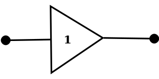
A tristate buffer can be thought of as a switch. If B is on, the switch is closed. If B is off, the switch is open.
Uses
The basic concept of the third state, high impedance (Hi-Z), is to effectively remove the device's influence from the rest of the circuit. If more than one device is electrically connected to another device, putting an output into the Hi-Z state is often used to prevent short circuits, or one device driving high (logical 1) against another device driving low (logical 0).
Three-state buffers can also be used to implement efficient multiplexers, especially those with large numbers of inputs.[1]
Three-state buffers are essential to the operation of a shared electronic bus.
Three-state logic can reduce the number of wires needed to drive a set of LEDs (tri-state multiplexing or Charlieplexing).
Output enable vs. chip select
Many memory devices designed to connect to a bus (such as RAM and ROM chips) have both CS (chip select) and OE (output enable) pins, which superficially appear to do the same thing. If CS is not asserted, the outputs are high impedance.
The difference lies in the time needed to output the signal. When chip select is deasserted, the chip does not operate internally, and there will be a significant delay between providing an address and receiving the data. (An advantage of course, is that the chip consumes minimal power in this case.)
When chip select is asserted, the chip internally performs the access, and only the final output drivers are disabled by deasserting output enable. This can be done while the bus is in use for other purposes, and when output enable is finally asserted, the data will appear with minimal delay. A ROM or static RAM chip with an output enable line will typically list two access times: one from chip select asserted and address valid, and a second, shorter time beginning when output enable is asserted.
Use of pull-ups and pull-downs
When outputs are tri-stated (in the Hi-Z state) their influence on the rest of the circuit is removed, and the circuit node will be "floating" if no other circuit element determines its state. Circuit designers will often use pull-up or pull-down resistors (usually within the range of 1–100kΩ) to influence the circuit when the output is tri-stated.
The PCI local bus provides pull-up resistors, but they would require several clock cycles to pull a signal high given the bus's large distributed capacitance. To enable high-speed operation, the protocol requires that every device connecting to the bus drive the important control signals high for at least one clock cycle before going to the Hi-Z state. This way, the pull-up resistors are only responsible for maintaining the bus signals in the face of leakage current.
Intel refers to this convention as "sustained tri-state", and also uses it in the Low Pin Count bus.
Alternatives to a three-state bus
The open collector input/output is a popular alternative to three-state logic. For example, the I²C bus protocol (a bi-directional communication bus protocol often used between devices) specifies the use of pull-up resistors on the two communication lines. When devices are inactive, they "release" the communication lines and tri-state their outputs, thus removing their influence on the circuit. When all the devices on the bus have "released" the communication lines, the only influence on the circuit is the pull-up resistors, which pull the lines high. When a device wants to communicate, it comes out of the Hi-Z state and drives the line low. Devices communicating using this protocol either let the line float high, or drive it low– thus preventing any bus contention situation where one device drives a line high and another low.
Usage of three-state logic is not recommended for on-chip connections but rather for inter-chip connections.[2]
Three-state buffers, when used to enable multiple devices to communicate on a data bus, can be functionally replaced by a multiplexer.[3] That will help select output from a range of devices and write one to the bus.
↑ 경종민, On-Chip Buses/Networks for SoC "On-Chip Buses [have] No use of tri-state signals [because] Tri-state bus is difficult for static timing analysis"
A logic gate is a device that performs a Boolean function, a logical operation performed on one or more binary inputs that produces a single binary output. Depending on the context, the term may refer to an ideal logic gate, one that has, for instance, zero rise time and unlimited fan-out, or it may refer to a non-ideal physical device.
In electronics, a comparator is a device that compares two voltages or currents and outputs a digital signal indicating which is larger. It has two analog input terminals and and one binary digital output . The output is ideally
Transistor–transistor logic (TTL) is a logic family built from bipolar junction transistors. Its name signifies that transistors perform both the logic function and the amplifying function, as opposed to earlier resistor–transistor logic (RTL) and diode–transistor logic (DTL).
In digital logic, an inverter or NOT gate is a logic gate which implements logical negation. It outputs a bit opposite of the bit that is put into it. The bits are typically implemented as two differing voltage levels.
I2C (Inter-Integrated Circuit; pronounced as “eye-squared-see” or “eye-two-see”), alternatively known as I2C or IIC, is a synchronous, multi-controller/multi-target (historically-termed as master/slave), single-ended, serial communication bus invented in 1982 by Philips Semiconductors. It is widely used for attaching lower-speed peripheral ICs to processors and microcontrollers in short-distance, intra-board communication.
In digital electronics, the fan-out is the number of gate inputs driven by the output of another single logic gate.
The 7400 series is a popular logic family of transistor–transistor logic (TTL) integrated circuits (ICs).
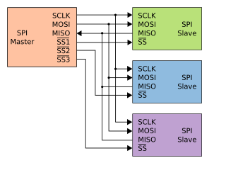
Serial Peripheral Interface (SPI) is a de facto standard for synchronous serial communication, used primarily in embedded systems for short-distance wired communication between integrated circuits.
In electronics, a Schmitt trigger is a comparator circuit with hysteresis implemented by applying positive feedback to the noninverting input of a comparator or differential amplifier. It is an active circuit which converts an analog input signal to a digital output signal. The circuit is named a trigger because the output retains its value until the input changes sufficiently to trigger a change. In the non-inverting configuration, when the input is higher than a chosen threshold, the output is high. When the input is below a different (lower) chosen threshold the output is low, and when the input is between the two levels the output retains its value. This dual threshold action is called hysteresis and implies that the Schmitt trigger possesses memory and can act as a bistable multivibrator. There is a close relation between the two kinds of circuits: a Schmitt trigger can be converted into a latch and a latch can be converted into a Schmitt trigger.
The IEEE 1164 standard is a technical standard published by the IEEE in 1993. It describes the definitions of logic values to be used in electronic design automation, for the VHDL hardware description language. It was sponsored by the Design Automation Standards Committee of the Institute of Electrical and Electronics Engineers (IEEE). The standardization effort was based on the donation of the Synopsys MVL-9 type declaration.
1-Wire is a wired half-duplex serial bus designed by Dallas Semiconductor that provides low-speed (16.3 kbit/s) data communication and supply voltage over a single conductor.
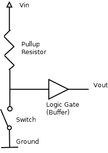
In electronic logic circuits, a pull-up resistor (PU) or pull-down resistor (PD) is a resistor used to ensure a known state for a signal. It is typically used in combination with components such as switches and transistors, which physically interrupt the connection of subsequent components to ground or to VCC. Closing the switch creates a direct connection to ground or VCC, but when the switch is open, the rest of the circuit would be left floating.
Open collector, open drain, open emitter, and open source refer to integrated circuit (IC) output pin configurations that process the IC's internal function through a transistor with an exposed terminal that is internally unconnected. One of the IC's internal high or low voltage rails typically connects to another terminal of that transistor. When the transistor is off, the output is internally disconnected from any internal power rail, a state called "high-impedance" (Hi-Z). Open outputs configurations thus differ from push–pull outputs, which use a pair of transistors to output a specific voltage or current.
In integrated circuit design, dynamic logic is a design methodology in combinational logic circuits, particularly those implemented in metal–oxide–semiconductor (MOS) technology. It is distinguished from the so-called static logic by exploiting temporary storage of information in stray and gate capacitances. It was popular in the 1970s and has seen a recent resurgence in the design of high-speed digital electronics, particularly central processing units (CPUs). Dynamic logic circuits are usually faster than static counterparts and require less surface area, but are more difficult to design. Dynamic logic has a higher average rate of voltage transitions than static logic, but the capacitive loads being transitioned are smaller so the overall power consumption of dynamic logic may be higher or lower depending on various tradeoffs. When referring to a particular logic family, the dynamic adjective usually suffices to distinguish the design methodology, e.g. dynamic CMOS or dynamic SOI design.
In electronics, high impedance means that a point in a circuit allows a relatively small amount of current through, per unit of applied voltage at that point. High impedance circuits are low current and potentially high voltage, whereas low impedance circuits are the opposite. Numerical definitions of "high impedance" vary by application.
In digital circuits, a logic level is one of a finite number of states that a digital signal can inhabit. Logic levels are usually represented by the voltage difference between the signal and ground, although other standards exist. The range of voltage levels that represent each state depends on the logic family being used. A logic-level shifter can be used to allow compatibility between different circuits.
Charlieplexing is a technique for accessing a large number of LEDs, switches, micro-capacitors or other I/O entities, using very few tri-state logic wires from a microcontroller, these entities being wired as discrete components, x/y arrays, or woven in a diagonally intersecting pattern to form diagonal arrays.
Chip select (CS) or slave select (SS) is the name of a control line in digital electronics used to select one of integrated circuits out of several connected to the same computer bus, usually utilizing the three-state logic.
A bus-holder or bus-keeper is a weak latch circuit that holds the last value on a tri-state bus.
A digital buffer is an electronic circuit element used to copy a digital input signal and isolate it from any output load. For the typical case of using voltages as logic signals, a logic buffer's input impedance is high, so it draws little current from the input circuit, to avoid disturbing its signal.
This page is based on this Wikipedia article Text is available under the CC BY-SA 4.0 license; additional terms may apply. Images, videos and audio are available under their respective licenses.