Vacuum fluorescent display

Last updated
A full view of a typical vacuum fluorescent display used in a videocassette recorder Vacuum fluorescent 1.jpg
A full view of a typical vacuum fluorescent display used in a videocassette recorder
A close-up of the VFD highlighting the multiple filaments, tensioned by the sheet metal springs at the right of the image Vacuum fluorescent 2.jpg
A close-up of the VFD highlighting the multiple filaments, tensioned by the sheet metal springs at the right of the image
Vacuum fluorescent display from a CD and dual cassette Hi-Fi. All segments are visible due to external ultraviolet illumination. VFD2.jpg
Vacuum fluorescent display from a CD and dual cassette Hi-Fi. All segments are visible due to external ultraviolet illumination.
Different VFD tubes
Digiziff-rot90.jpg Sharp EL-8 Display 8 Digits Green Itron Fluorescent Tubes (cropped).jpg Indikator IV-4 cropped.JPG
7 segments
8 segments
(Sharp EL-8)
16 segments

A vacuum fluorescent display (VFD) is a display device once commonly used on consumer electronics equipment such as video cassette recorders, car radios, and microwave ovens.

Contents

A VFD operates on the principle of cathodoluminescence, roughly similar to a cathode ray tube, but operating at much lower voltages. Each tube in a VFD has a phosphor-coated carbon anode that is bombarded by electrons emitted from the cathode filament. [1] [2] In fact, each tube in a VFD is a triode vacuum tube because it also has a mesh control grid. [3]

Unlike liquid crystal displays (LCDs), a VFD emits very bright light with high contrast and can support display elements of various colors. Standard illumination figures for VFDs are around 640 cd/m2 with high-brightness VFDs operating at 4,000 cd/m2, and experimental units as high as 35,000 cd/m2 depending on the drive voltage and its timing. [3] The choice of color (which determines the nature of the phosphor) and display brightness significantly affect the lifetime of the tubes, which can range from as low as 1,500 hours for a vivid red VFD to 30,000 hours for the more common green ones. [3] Cadmium was commonly used in the phosphors of VFDs in the past, but the current RoHS-compliant VFDs have eliminated this metal from their construction, using instead phosphors consisting of a matrix of alkaline earth and very small amounts of group III metals, doped with very small amounts of rare earth metals. [4]

VFDs can display seven-segment numerals, multi-segment alpha-numeric characters or can be made in a dot-matrix to display different alphanumeric characters and symbols. In practice, there is little limit to the shape of the image that can be displayed: it depends solely on the shape of phosphor on the anode(s).

The first VFD was the single indication DM160 by Philips in 1959. [5] The first multi-segment VFD was a 1967 Japanese single-digit, seven-segment device made by Ise Electronics Corporation. [6] The displays became common on calculators and other consumer electronics devices. [7] In the late 1980s hundreds of millions of units were made yearly. [8]

Design

Macro image of a VFD digit with 3 horizontal tungsten wires and control grid Vacuum Fluorescent Digit.jpg
Macro image of a VFD digit with 3 horizontal tungsten wires and control grid

The device consists of a hot cathode (filaments), grids and anodes (phosphor) encased in a glass envelope under a high vacuum condition. The cathode is made up of fine tungsten wires, coated by alkaline earth metal oxides (barium, [2] strontium and calcium oxides [9] [10] ), which emit electrons when heated to 650 °C [2] by an electric current. These electrons are controlled and diffused by the grids (made using photochemical machining), which are made up of thin (50 micron thick) stainless steel. [2] If electrons impinge on the phosphor-coated anode plates, they fluoresce, emitting light. Unlike the orange-glowing cathodes of traditional vacuum tubes, VFD cathodes are efficient emitters at much lower temperatures, and are therefore essentially invisible. [11] The anode consists of a glass plate with electrically conductive traces (each trace is connected to a single indicator segment), which is coated with an insulator, which is then partially etched to create holes which are then filled with a conductor like graphite, which in turn is coated with phosphor. This transfers energy from the trace to the segment. The shape of the phosphor will determine the shape of the VFD's segments. The most widely used phosphor is Zinc-doped copper-activated Zinc oxide, [2] which generates light at a peak wavelength of 505 nm.

The cathode wire to which the oxides are applied is made of tungsten or ruthenium-tungsten alloy. The oxides in the cathodes are not stable in air, so they are applied to the cathode as carbonates, the cathodes are assembled into the VFD, and the cathodes are heated by passing a current through them while inside the vacuum of the VFD to convert the carbonates into oxides. [2] [10]

The principle of operation is identical to that of a vacuum tube triode. Electrons can only reach (and "illuminate") a given plate element if both the grid and the plate are at a positive potential with respect to the cathode. [12] This allows the displays to be organized as multiplexed displays where the multiple grids and plates form a matrix, minimizing the number of signal pins required. In the example of the VCR display shown to the right, the grids are arranged so that only one digit is illuminated at a time. All of the similar plates in all of the digits (for example, all of the lower-left plates in all of the digits) are connected in parallel. One by one, the microprocessor driving the display enables a digit by placing a positive voltage on that digit's grid and then placing a positive voltage on the appropriate plates. Electrons flow through that digit's grid and strike those plates that are at a positive potential. The microprocessor cycles through illuminating the digits in this way at a rate high enough to create the illusion of all digits glowing at once via persistence of vision.[ citation needed ]

The extra indicators (in our example, "VCR", "Hi-Fi", "STEREO", "SAP", etc.) are arranged as if they were segments of an additional digit or two or extra segments of existing digits and are scanned using the same multiplexed strategy as the real digits. Some of these extra indicators may use a phosphor that emits a different color of light, for example, orange.

The light emitted by most VFDs contains many colors and can often be filtered to enhance the color saturation providing a deep green or deep blue, depending on the whims of the product's designers. Phosphors used in VFDs are different from those in cathode-ray displays since they must emit acceptable brightness with only around 50 volts of electron energy, compared to several thousand volts in a CRT. [13] The insulating layer in a VFD is normally black, however it can be removed or made transparent to allow the display to be transparent. AMVFD displays that incorporate a driver IC are available for applications that require high image brightness and an increased number of pixels. Phosphors of different colors can be stacked on top of each other for achieving gradations and various color combinations. Hybrid VFDs include both fixed display segments and a graphic VFD in the same unit. VFDs may have display segments, grids and related circuitry on their front and rear glass panels, using a central cathode for both panels, allowing for increased segment density. The segments can also be placed exclusively on the front instead of on the back, improving viewing angles and brightness. [14] [15] [16] [17] [18] [19] [20] [21] [22]

Use

Besides brightness, VFDs have the advantages of being rugged, inexpensive, and easily configured to display a wide variety of customized messages, and unlike LCDs, VFDs are not limited by the response time of rearranging liquid crystals and are thus able to function normally in cold, even sub-zero, temperatures, making them ideal for outdoor devices in cold climates. Early on, the main disadvantage of such displays was their use of significantly more power (0.2 watts) than a simple LCD. This was considered a significant drawback for battery-operated equipment like calculators, so VFDs ended up being used mainly in equipment powered by an AC supply or heavy-duty rechargeable batteries.

A digital dashboard cluster in a 1992 Mercury Grand Marquis Vfd car.jpg
A digital dashboard cluster in a 1992 Mercury Grand Marquis

During the 1980s, this display began to be used in automobiles, especially where car makers were experimenting with digital displays for vehicle instruments such as speedometers and odometers. A good example of these were the high-end Subaru cars made in the early 1980s (referred to by Subaru enthusiasts as a digi-dash, or digital dashboard). The brightness of VFDs makes them well suited for use in cars. The Renault Espace Mk4 and Scenic Mk2 used VFD panels to show all functions on the dashboard including the radio and multi message panel. They are bright enough to read in full sunlight as well as dimmable for use at night. This panel uses four colors; the usual blue/green as well as deep blue, red and yellow/orange.

This technology was also used from 1979 to the mid-1980s in portable electronic game units. These games featured bright, clear displays but the size of the largest vacuum tubes that could be manufactured inexpensively kept the size of the displays quite small, often requiring the use of magnifying Fresnel lenses.[ citation needed ] While later games had sophisticated multi-color displays, early games achieved color effects using transparent filters to change the color of the (usually light blue) light emitted by the phosphors. High power consumption and high manufacturing cost contributed to the demise of the VFD as a videogame display. LCD games could be manufactured for a fraction of the price, did not require frequent changes of batteries (or AC adapters) and were much more portable. Since the late 1990s, backlit color active-matrix LCD displays have been able to cheaply reproduce arbitrary images in any color, a marked advantage over fixed-color, fixed-character VFDs. This is one of the main reasons for the decline in popularity of VFDs, although they continue to be made. Many low-cost DVD players still feature VFDs.

From the mid-1980s onwards, VFDs were used for applications requiring smaller displays with high brightness specifications, though now the adoption of high-brightness organic light-emitting diodes (OLEDs) is pushing VFDs out of these markets.

Vacuum fluorescent displays were once commonly used as floor indicators for elevators by Otis Elevator Company worldwide and Montgomery Elevator Company in North America (the former from the early 1980s to the late-2000s in the form of (usually two) green 16-segment displays, and the latter from the mid 1980s to the early 2000s in the form of (usually 3) green or blue 10x14 dot-matrix displays, one for the arrow and the other two for the digits).

In addition to the widely used fixed character VFD, a graphic type made of an array of individually addressable pixels is also available. These more sophisticated displays offer the flexibility of displaying arbitrary images, and may still be a useful choice for some types of consumer equipment.

Multiplexing may be used in VFDs to reduce the number of connections necessary to drive the display. [2]

Use as amplifier

Several radio amateurs have experimented with the possibilities of using VFDs as triode amplifiers. [23] [24] [25] In 2015, Korg released the Nutube, an analogue audio amplifier component based on VFD technology. The Nutube is used in applications such as guitar amplifiers from Vox [26] and the Apex Sangaku headphone amplifier. [27] The Nutube is sold by Korg but made by Noritake Itron. [28]

Fade

Fading is sometimes a problem with VFDs. Light output drops over time due to falling emission and reduction of phosphor efficiency. How quickly and how far this falls depends on the construction and operation of the VFD. In some equipment, loss of VFD output can render the equipment inoperable. Fading can be slowed by using a display driver chip to lower the voltages necessary to drive a VFD. Fading can also occur due to evaporation and contamination of the cathode. Phosphors that contain sulfur are more susceptible to fading. [2]

Emission may usually be restored by raising filament voltage. Thirty-three percent voltage boost can rectify moderate fade, and 66% boost severe fade.[ citation needed ] This can make the filaments visible in use, though the usual green-blue VFD filter helps reduce any such red or orange light from the filament.

History

A PCB with VFD display from a Casio M-1 Calculator, produced between 1976 and 1986 Casio M-1 Calculator.jpg
A PCB with VFD display from a Casio M-1 Calculator, produced between 1976 and 1986

Of the three prevalent display technologies – VFD, LCD, and LED – the VFD was the first to be developed. It was used in early handheld calculators. LED displays displaced VFDs in this use as the very small LEDs used required less power, thereby extending battery life, though early LED displays had problems achieving uniform brightness levels across all display segments. Later, LCDs displaced LEDs, offering even lower power requirements.

The first VFD was the single indication DM160 by Philips in 1959. It could easily be driven by transistors, so was aimed at computer applications as it was easier to drive than a neon and had longer life than a light bulb. The 1967 Japanese single digit seven segment display in terms of anode was more like the Philips DM70 / DM71 Magic Eye as the DM160 has a spiral wire anode. The Japanese seven segment VFD meant that no patent royalties needed to be paid on desk calculator displays as would have been the case using Nixie tubes or Panaplex neon digits. In the UK the Philips designs were made and marketed by Mullard (almost wholly owned by Philips even before WWII).

The Russian IV-15 VFD tube is very similar to the DM160. The DM160, DM70/DM71 and Russian IV-15 can (like a VFD panel) be used as triodes. The DM160 is thus the smallest VFD and smallest triode valve. The IV-15 is slightly different shape (see photo of DM160 and IV-15 for comparison).

See also

Related Research Articles

<span class="mw-page-title-main">Cathode-ray tube</span> Vacuum tube often used to display images

A cathode-ray tube (CRT) is a vacuum tube containing one or more electron guns, which emit electron beams that are manipulated to display images on a phosphorescent screen. The images may represent electrical waveforms on an oscilloscope, a frame of video on an analog television set (TV), digital raster graphics on a computer monitor, or other phenomena like radar targets. A CRT in a TV is commonly called a picture tube. CRTs have also been used as memory devices, in which case the screen is not intended to be visible to an observer. The term cathode ray was used to describe electron beams when they were first discovered, before it was understood that what was emitted from the cathode was a beam of electrons.

<span class="mw-page-title-main">Cathode</span> Electrode where reduction takes place

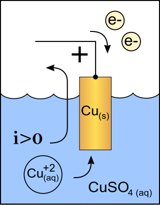
A cathode is the electrode from which a conventional current leaves a polarized electrical device. This definition can be recalled by using the mnemonic CCD for Cathode Current Departs. A conventional current describes the direction in which positive charges move. Electrons have a negative electrical charge, so the movement of electrons is opposite to that of the conventional current flow. Consequently, the mnemonic cathode current departs also means that electrons flow into the device's cathode from the external circuit. For example, the end of a household battery marked with a + (plus) is the cathode.

<span class="mw-page-title-main">Triode</span> Single-grid amplifying vacuum tube having three active electrodes

A triode is an electronic amplifying vacuum tube consisting of three electrodes inside an evacuated glass envelope: a heated filament or cathode, a grid, and a plate (anode). Developed from Lee De Forest's 1906 Audion, a partial vacuum tube that added a grid electrode to the thermionic diode, the triode was the first practical electronic amplifier and the ancestor of other types of vacuum tubes such as the tetrode and pentode. Its invention helped make amplified radio technology and long-distance telephony possible. Triodes were widely used in consumer electronics devices such as radios and televisions until the 1970s, when transistors replaced them. Today, their main remaining use is in high-power RF amplifiers in radio transmitters and industrial RF heating devices. In recent years there has been a resurgence in demand for low power triodes due to renewed interest in tube-type audio systems by audiophiles who prefer the sound of tube-based electronics.

<span class="mw-page-title-main">Vacuum tube</span> Device that controls current between electrodes

A vacuum tube, electron tube, valve, or tube, is a device that controls electric current flow in a high vacuum between electrodes to which an electric potential difference has been applied.

<span class="mw-page-title-main">Nixie tube</span> Electronic numeric display device

A Nixie tube, or cold cathode display, is an electronic device used for displaying numerals or other information using glow discharge.

A tetrode is a vacuum tube having four active electrodes. The four electrodes in order from the centre are: a thermionic cathode, first and second grids, and a plate. There are several varieties of tetrodes, the most common being the screen-grid tube and the beam tetrode. In screen-grid tubes and beam tetrodes, the first grid is the control grid and the second grid is the screen grid. In other tetrodes one of the grids is a control grid, while the other may have a variety of functions.

<span class="mw-page-title-main">Cold cathode</span> Type of electrode and part of cold cathode fluorescent lamp.

A cold cathode is a cathode that is not electrically heated by a filament. A cathode may be considered "cold" if it emits more electrons than can be supplied by thermionic emission alone. It is used in gas-discharge lamps, such as neon lamps, discharge tubes, and some types of vacuum tube. The other type of cathode is a hot cathode, which is heated by electric current passing through a filament. A cold cathode does not necessarily operate at a low temperature: it is often heated to its operating temperature by other methods, such as the current passing from the cathode into the gas.

<span class="mw-page-title-main">Electron gun</span> Electrical component producing a narrow electron beam

An electron gun is an electrical component in some vacuum tubes that produces a narrow, collimated electron beam that has a precise kinetic energy.

<span class="mw-page-title-main">Control grid</span> Electrode used to control electron flow within a vacuum tube

The control grid is an electrode used in amplifying thermionic valves such as the triode, tetrode and pentode, used to control the flow of electrons from the cathode to the anode (plate) electrode. The control grid usually consists of a cylindrical screen or helix of fine wire surrounding the cathode, and is surrounded in turn by the anode. The control grid was invented by Lee De Forest, who in 1906 added a grid to the Fleming valve to create the first amplifying vacuum tube, the Audion (triode).

<span class="mw-page-title-main">Gas-filled tube</span> Assembly of electrodes at either end of an insulated tube filled with gas

A gas-filled tube, also commonly known as a discharge tube or formerly as a Plücker tube, is an arrangement of electrodes in a gas within an insulating, temperature-resistant envelope. Gas-filled tubes exploit phenomena related to electric discharge in gases, and operate by ionizing the gas with an applied voltage sufficient to cause electrical conduction by the underlying phenomena of the Townsend discharge. A gas-discharge lamp is an electric light using a gas-filled tube; these include fluorescent lamps, metal-halide lamps, sodium-vapor lamps, and neon lights. Specialized gas-filled tubes such as krytrons, thyratrons, and ignitrons are used as switching devices in electric devices.

<span class="mw-page-title-main">Field-emission display</span>

A field-emission display (FED) is a flat panel display technology that uses large-area field electron emission sources to provide electrons that strike colored phosphor to produce a color image. In a general sense, an FED consists of a matrix of cathode ray tubes, each tube producing a single sub-pixel, grouped in threes to form red-green-blue (RGB) pixels. FEDs combine the advantages of CRTs, namely their high contrast levels and very fast response times, with the packaging advantages of LCD and other flat-panel technologies. They also offer the possibility of requiring less power, about half that of an LCD system. FEDs can also be made transparent.

<span class="mw-page-title-main">Pentode</span> Vacuum tube with five electrodes

A pentode is an electronic device having five electrodes. The term most commonly applies to a three-grid amplifying vacuum tube or thermionic valve that was invented by Gilles Holst and Bernhard D.H. Tellegen in 1926. The pentode was developed from the screen-grid tube or shield-grid tube by the addition of a grid between the screen grid and the plate. The screen-grid tube was limited in performance as an amplifier due to secondary emission of electrons from the plate. The additional grid is called the suppressor grid. The suppressor grid is usually operated at or near the potential of the cathode and prevents secondary emission electrons from the plate from reaching the screen grid. The addition of the suppressor grid permits much greater output signal amplitude to be obtained from the plate of the pentode in amplifier operation than from the plate of the screen-grid tube at the same plate supply voltage. Pentodes were widely manufactured and used in electronic equipment until the 1960s to 1970s, during which time transistors replaced tubes in new designs. During the first quarter of the 21st century, a few pentode tubes have been in production for high power radio frequency applications, musical instrument amplifiers, home audio and niche markets.

<span class="mw-page-title-main">Hot-filament ionization gauge</span>

The hot-filament ionization gauge, sometimes called a hot-filament gauge or hot-cathode gauge, is the most widely used low-pressure (vacuum) measuring device for the region from 10−3 to 10−10 Torr. It is a triode, with the filament being the cathode.

<span class="mw-page-title-main">Hot cathode</span> Type of electrode

In vacuum tubes and gas-filled tubes, a hot cathode or thermionic cathode is a cathode electrode which is heated to make it emit electrons due to thermionic emission. This is in contrast to a cold cathode, which does not have a heating element. The heating element is usually an electrical filament heated by a separate electric current passing through it. Hot cathodes typically achieve much higher power density than cold cathodes, emitting significantly more electrons from the same surface area. Cold cathodes rely on field electron emission or secondary electron emission from positive ion bombardment, and do not require heating. There are two types of hot cathode. In a directly heated cathode, the filament is the cathode and emits the electrons. In an indirectly heated cathode, the filament or heater heats a separate metal cathode electrode which emits the electrons.

Ultra-linear electronic circuits are those used to couple a tetrode or pentode vacuum-tube to a load.

<span class="mw-page-title-main">Fleming valve</span> Type of vacuum tube; early radio detector

The Fleming valve, also called the Fleming oscillation valve, was a thermionic valve or vacuum tube invented in 1904 by English physicist John Ambrose Fleming as a detector for early radio receivers used in electromagnetic wireless telegraphy. It was the first practical vacuum tube and the first thermionic diode, a vacuum tube whose purpose is to conduct current in one direction and block current flowing in the opposite direction. The thermionic diode was later widely used as a rectifier — a device that converts alternating current (AC) into direct current (DC) — in the power supplies of a wide range of electronic devices, until beginning to be replaced by the selenium rectifier in the early 1930s and almost completely replaced by the semiconductor diode in the 1960s. The Fleming valve was the forerunner of all vacuum tubes, which dominated electronics for 50 years. The IEEE has described it as "one of the most important developments in the history of electronics", and it is on the List of IEEE Milestones for electrical engineering.

<span class="mw-page-title-main">Magic eye tube</span> Visual indicator of the amplitude of an electronic signal

A magic eye tube or tuning indicator, in technical literature called an electron-ray indicator tube, is a vacuum tube which gives a visual indication of the amplitude of an electronic signal, such as an audio output, radio-frequency signal strength, or other functions. The magic eye is a specific type of such a tube with a circular display similar to the EM34 illustrated. Its first broad application was as a tuning indicator in radio receivers, to give an indication of the relative strength of the received radio signal, to show when a radio station was properly tuned in.

The inductive output tube (IOT) or klystrode is a variety of linear-beam vacuum tube, similar to a klystron, used as a power amplifier for high frequency radio waves. It evolved in the 1980s to meet increasing efficiency requirements for high-power RF amplifiers in radio transmitters. The primary commercial use of IOTs is in UHF television transmitters, where they have mostly replaced klystrons because of their higher efficiencies and smaller size. IOTs are also used in particle accelerators. They are capable of producing power output up to about 30 kW continuous and 7 MW pulsed and gains of 20–23 dB at frequencies up to about a gigahertz.

<span class="mw-page-title-main">Barkhausen–Kurz tube</span>


The Barkhausen–Kurz tube, also called the retarding-field tube, reflex triode, B–K oscillator, and Barkhausen oscillator was a high frequency vacuum tube electronic oscillator invented in 1920 by German physicists Heinrich Georg Barkhausen and Karl Kurz. It was the first oscillator that could produce radio power in the ultra-high frequency (UHF) portion of the radio spectrum, above 300 MHz. It was also the first oscillator to exploit electron transit time effects. It was used as a source of high frequency radio waves in research laboratories, and in a few UHF radio transmitters through World War 2. Its output power was low which limited its applications. However it inspired research that led to other more successful transit time tubes such as the klystron, which made the low power Barkhausen-Kurz tube obsolete.

References

  1. Shigeo Shionoya; William M. Yen (1998). Phosphor Handbook. CRC Press. p. 561. ISBN   978-0-8493-7560-6.
  2. 1 2 3 4 5 6 7 8 Chen, J., Cranton, W., & Fihn, M. (Eds.). (2016). Handbook of Visual Display Technology. doi:10.1007/978-3-319-14346-0 page 1610 onwards
  3. 1 2 3 Janglin Chen; Wayne Cranton; Mark Fihn (2011). Handbook of Visual Display Technology. Springer. pp. 1056, 1067–1068. ISBN   978-3-540-79566-7.
  4. "Fluorescent phosphorescent coating free from sulphur and cadmium". Archived from the original on 2021-02-02. Retrieved 2020-10-03.
  5. (HB9RXQ), Ernst Erb. "DM 160, Tube DM160; Röhre DM 160 ID19445, INDICATOR, in gene". www.radiomuseum.org. Archived from the original on 2012-01-13. Retrieved 2012-08-13.{{cite web}}: CS1 maint: numeric names: authors list (link)
  6. Kiyozumi, K., & Nakamura, T. (1983). Vacuum fluorescent displays: from single digits to colour TV. Displays, 4(4), 213–220. doi:10.1016/0141-9382(83)90116-6
  7. Joseph A. Castellano (ed), Handbook of display technology Gulf Professional Publishing, 1992 ISBN   0-12-163420-5 page 9
  8. Joseph A. Castellano (ed), Handbook of display technology Gulf Professional Publishing, 1992 ISBN   0-12-163420-5 page 176
  9. "VFD|Futaba Corporation". www.futaba.co.jp. Archived from the original on 2019-12-20. Retrieved 2019-12-15.
  10. 1 2 "Directly-heated oxide cathode and fluorescent display tube using the same". Archived from the original on 2021-02-02. Retrieved 2020-10-29.
  11. Joseph A. Castellano (ed), Handbook of display technology, Gulf Professional Publishing, 1992 ISBN   0-12-163420-5 Chapter 7 Vacuum Fluorescent Displays pp. 163 and following
  12. Elektrotechnik Tabellen Kommunikationselektronik (3rd ed.). Braunschweig, Germany: Westermann. 1999. p. 110. ISBN   3142250379.
  13. William M. Yen, Shigeo Shionoya, Hajime Yamamoto (editors), Phosphor Handbook, CRC Press, 2007 ISBN   0-8493-3564-7 Chapter 8
  14. "Front Luminous VFD|Futaba Corporation". www.futaba.co.jp. 27 February 2021. Archived from the original on 21 December 2019. Retrieved 4 January 2020.
  15. "Bi-Planar VFD|Futaba Corporation". www.futaba.co.jp. 27 February 2021. Archived from the original on 21 December 2019. Retrieved 4 January 2020.
  16. "Gradation VFD|Futaba Corporation". www.futaba.co.jp. 27 February 2021. Archived from the original on 21 December 2019. Retrieved 4 January 2020.
  17. "Hybrid VFD|Futaba Corporation". www.futaba.co.jp. 27 February 2021. Archived from the original on 21 December 2019. Retrieved 4 January 2020.
  18. "VFD (Vacuum Fluorescent Display) | Products | NORITAKE ITRON CORPORATION". www.noritake-itron.jp. Archived from the original on 2018-06-19. Retrieved 2020-01-04.
  19. "Chip In Glass VFD(CIG VFD)|Futaba Corporation". www.futaba.co.jp. 27 February 2021. Archived from the original on 18 January 2020. Retrieved 4 January 2020.
  20. "Double Layer Phosphor Printing VFD|Futaba Corporation". www.futaba.co.jp. 27 February 2021. Archived from the original on 21 December 2019. Retrieved 4 January 2020.
  21. "Ultra-high luminance, full dot matrix display|Futaba Corporation". www.futaba.co.jp. 27 February 2021. Archived from the original on 21 December 2019. Retrieved 4 January 2020.
  22. "Clear Background VFD|Futaba Corporation". www.futaba.co.jp. 27 February 2021. Archived from the original on 21 December 2019. Retrieved 4 January 2020.
  23. N9WOS (29 July 2005). "VFD as an audio/RF amplifier?". Electronics Point forums. Archived from the original on 11 March 2018. Retrieved 11 March 2018.{{cite web}}: CS1 maint: numeric names: authors list (link)
  24. "H. P. Friedrichs, Vacuum Fluorescent Display Amplifiers For Primitive Radio, eHam.net December 2008, retrieved 2010 Feb 8". Eham.net. Archived from the original on 2009-08-26. Retrieved 2012-12-11.
  25. "Des. Kostryca, A VFD Receiver (Triodes in Disguise), eHam.net January 2009, retrieved 2010 Feb 8". Eham.net. Retrieved 2012-12-11.
  26. "Vox MV50 AC guitar amplifier". Archived from the original on 16 March 2018. Retrieved 11 March 2018.
  27. "The Sangaku headphone amplifier". Archived from the original on 22 April 2018. Retrieved 11 March 2018.
  28. "News | KORG INC and Noritake Co., Limited Release Innovative Vacuum Tube: The Nutube | KORG (USA)". Archived from the original on 2020-11-01. Retrieved 2020-10-29.
  29. "Calculator.org website". Archived from the original on 23 July 2023. Retrieved 23 July 2023.