A venturi scrubber is designed to effectively use the energy from a high-velocity inlet gas stream to atomize the liquid being used to scrub the gas stream. This type of technology is a part of the group of air pollution controls collectively referred to as wet scrubbers.
Venturis can be used to collect both particulate and gaseous pollutants, but although the liquid surface area provided is quite large they are more effective in removing particles since particles can be trapped by contact, but gases must be trapped by absorption during the relatively short exposure time.
Venturi devices have also been used for over 100 years to measure fluid flow (Venturi tubes derived their name from Giovanni Battista Venturi, an Italian physicist). In the late 1940s, H.F. Johnstone[1], William Jones,[2] and other researchers found that they could effectively use the venturi configuration to remove particles from gas streams. Figure 1 illustrates the classic venturi configuration.[3]
An ejector or jetventuri scrubber is an industrial pollution control device, usually installed on the exhaust flue gas stacks of large furnaces, but may also be used on any number of other air exhaust systems. They differ from other venturi scrubbers energy is derived from the high-pressure spray of liquid from a nozzle rather than the flow of process gas, allowing the scrubber to also act as a vacuum ejector and draw process gas through the device without external assistance.
A venturi scrubber consists of three sections: a converging section, a throat section, and a diverging section. The inlet gas stream enters the converging section and, as the area decreases, gas velocity increases. Liquid is introduced either at the throat or at the entrance to the converging section. The inlet gas, forced to move at extremely high velocities in the small throat section, turbulently mixes with the liquid, producing an enormous number of very tiny droplets. Particle and gas removal occur in the diverging section as the inlet gas stream mixes with the fog of tiny liquid droplets. The inlet stream then exits through the diverging section, where it is forced to slow down.
If liquid is introduced above the converging section and coats the walls up to the throat, then the venturi is described as having a "wet wall" or "wetted throat" as seen in Figure 2. This method allows particulates in the stream that may be prone to caking onto surfaces to be washed away and reduces the mechanical abrasion of particles hitting the throat at high speed. It is very effective for handling hot, dry inlet gases that contain dust, or particles which are abrasive or corrosive, such as kiln or furnace gases.
Wetting of the throat can be achieved with a spray directed at the walls or with a weir encircling the converging section which water flows over. This method can be used only at liquid injection source as the high velocity gas will shear droplets from the walls. Liquid can also be introduced by spray nozzles directly into the gas stream and for low gas flow velocities this may provide more efficient operation, either or both methods may be employed depending on the application.
Simple venturis have fixed throat areas and so will only operate efficiently over a certain range of flow rates. Adjustable-throat venturis allow efficiency to be maintained over a much larger range of flows by changing the size of the throat in accordance with the gas flow rate. Certain types of orifices (throat areas) that create more turbulence than a true venturi were found to be equally efficient for a given unit of energy consumed and the results of these findings led to the development of the annular-orifice, or adjustable-throat, venturi scrubber (Figure 5).[3] The size of the throat area is varied by moving a plunger, or adjustable disk, up or down in the throat, thereby decreasing or increasing the annular opening. Gas flows through the annular opening and atomizes liquid that is sprayed onto the plunger or swirled in from the top.
Wetted-throat venturis with round throats (Figures 2 and 3) can handle inlet flows as large as 88,000 m3/h (40,000 cfm).[4] At inlet flow rates greater than this, achieving uniform liquid distribution is difficult, unless additional weirs or baffles are used. To handle large inlet flows, scrubbers designed with long, narrow, rectangular throats (Figure 4) have been used.[3] The rectangular-throat venturi is often built to be adjustable by introducing moving plates or flaps into the throat, as shown in Figure 6. A water-wash spray is used to continually wash collected material from the plate.
Another modification can be seen in the venturi-rod or rod deck scrubber. By placing a number of pipes parallel to each other, a series of longitudinal venturi openings can be created as shown in Figure 7.[3] The area between adjacent rods is a small venturi throat. Water sprays help prevent solids buildup. The principal atomization of the liquid occurs at the rods, where the high-velocity gas moving through spacings creates the small droplets necessary for fine particle collection. This method can produce very high water droplet densities in the gas stream due to a very high throat perimeter compared to other types. These rods must be made of abrasion-resistant material due to the high velocities present.
All venturi scrubbers require an entrainment separator because the high velocity of gas through the scrubber will have a tendency to entrain the droplets with the outlet clean gas stream. Cyclonic, mesh-pad, and blade separators are all used to remove liquid droplets from the flue gas and return the liquid to the scrubber water.
Ejector venturi scrubber
Like a spray tower an ejector venturi scrubber uses a preformed spray. However, in an ejector venturi scrubber only a single nozzle is used instead of many nozzles. This nozzle operates at higher pressures and higher injection rates than those in most spray chambers. The high-pressure spray nozzle (up to 689 kPa or 100 psig) is aimed at the throat section of a venturi constriction.
The ejector venturi is unique among available scrubbing systems since it can move the process gas without the aid of a fan or blower. The liquid spray coming from the nozzle creates a partial vacuum in the side duct of the scrubber. The partial vacuum is due to the Bernoulli effect, and is similar to water aspirators used in chemistry labs. This partial vacuum can be used to move the process gas through the venturi as well as through the facility's process system. In the case of easily-clogging material, explosive gasses, or extremely corrosive atmospheres, the elimination of a fan in the system can avoid many potential problems.
The energy for the formation of scrubbing droplets comes from the injected liquid. The high pressure sprays passing through the venturi throat form numerous fine liquid droplets that provide turbulent mixing between the gas and liquid phases. Very high liquid-injection rates are used to provide the gas-moving capability and higher collection efficiencies. As with other types of venturis, a means of separating entrained liquid from the gas stream must be installed. Entrainment separators are commonly used to remove remaining small droplets.
Particle collection
Figure 5 - Adjustable-throat venturi scrubber with plunger
The atomized liquid provides an enormous number of tiny droplets for the dust particles to impact on. These liquid droplets incorporating the particles must be removed from the scrubber outlet stream, generally by cyclonic separators.
Particle removal efficiency increases with increasing pressure drop because of increased turbulence due to high gas velocity in the throat. Venturis can be operated with pressure drops ranging from 12millibar to 250millibar.
Most venturis normally operate with pressure drops in the range of 50 to 150cm (20 to 60 in) of water. At these pressure drops, the gas velocity in the throat section is usually between 30 and 120m/s (100 to 400ft/s), or approximately 270mph at the high end. These high pressure drops result in high operating costs.
The liquid-injection rate, or liquid-to-gas ratio (L/G), also affects particle collection. The proper amount of liquid must be injected to provide adequate liquid coverage over the throat area and make up for any evaporation losses. If there is insufficient liquid, then there will not be enough liquid targets to provide the required capture efficiency.
Most venturi systems operate with an L/G ratio of 0.4 to 1.3 L/m3 (3 to 10 gal/1000ft3).[4] L/G ratios less than 0.4 L/m3 (3 gal/1000ft3) are usually not sufficient to cover the throat, and adding more than 1.3 L/m3 (10 gal/1000ft3) does not usually significantly improve particle collection efficiency.
Ejector venturi scrubber
Ejector venturis are effective in removing particles larger than 1.0μm in diameter. These scrubbers are not used on submicrometer-sized particles unless the particles are condensable.[5] Particle collection occurs primarily by impaction as the exhaust gas (from the process) passes through the spray.
The turbulence that occurs in the throat area also causes the particles to contact the wet droplets and be collected. Particle collection efficiency increases with an increase in nozzle pressure and/or an increase in the liquid-to-gas ratio. Increases in either of these two operating parameters will also result in an increase in pressure drop for a given system. Therefore, an increase in pressure drop also increases particle collection efficiency. Ejector venturis operate at higher L/G ratios than most other particulate scrubbers (i.e., 7 to 13 L/m3 compared to 0.4-2.7 L/m3 for most other designs), and often also require higher liquid pressures, especially if being used to drive the process gas.
Gas collection
Figure 6 - Adjustable-throat venturi scrubber with movable plate
Venturi scrubbers can be used for removing gaseous pollutants; however, they are not used when removal of gaseous pollutants is the only concern.
The high inlet gas velocities in a venturi scrubber result in a very short contact time between the liquid and gas phases. This short contact time limits gas absorption. However, because venturis have a relatively open design compared to other scrubbers, they are still very useful for simultaneous gaseous and particulate pollutant removal, especially when:
A high concentration of dust is in the inlet stream
The dust is sticky or has a tendency to plug openings
The gaseous contaminant is very soluble or chemically reactive with the liquid
To maximize the absorption of gases, venturis are designed to operate at a different set of conditions from those used to collect particles. The gas velocities are lower and the liquid-to-gas ratios are higher for absorption.
For a given venturi design, if the gas velocity is decreased, then the pressure drop (resistance to flow) will also decrease and vice versa. Therefore, by reducing pressure drop, the gas velocity is decreased and the corresponding residence time is increased. Liquid-to-gas ratios for these gas absorption applications are approximately 2.7 to 5.3 L/m3 (20 to 40 gal/1000ft3). The reduction in gas velocity allows for a longer contact time between phases and better absorption.
Increasing the liquid-to-gas ratio will increase the potential solubility of the pollutant in the liquid. This is why the ejector venturi scrubber is often used instead for this purpose, although other factors may still result in a typical venturi scrubber being chosen.
Though capable of some incidental control of volatile organic compounds (VOC), generally venturi scrubbers are limited to control PM (particulate matter) and high solubility or reactive gases (EPA, 1992; EPA, 1996).[6]
Ejector venturi scrubber
Ejector venturis have a short gas-liquid contact time because the exhaust gas velocities through the vessel are very high. This short contact time limits the absorption efficiency of the system. Although ejector venturis are not used primarily for gas removal, they can be effective if the gas is very soluble or if a very reactive scrubbing reagent is used. In these instances, removal efficiencies of as high as 95% can be achieved.[5]
Maintenance considerations
Figure 7 - Venturi rod scrubber
The primary maintenance problem for venturi scrubbers is wear, or abrasion, of the scrubber shell because of high gas velocities. Gas velocities in the throat can reach speeds of 430km/h (270mph). Particles and liquid droplets traveling at these speeds can rapidly erode the scrubber shell.
Abrasion can be reduced by lining the throat with silicon carbide brick or fitting it with a replaceable liner. Abrasion can also occur downstream of the throat section. To reduce abrasion here, the elbow at the bottom of the scrubber (leading into the separator) can be flooded (i.e. filled with a pool of scrubbing liquid). Particles and droplets impact on the pool of liquid, reducing wear on the scrubber shell.
A common technique to help reduce abrasion is to use a precleaner (i.e., quench sprays or cyclone) to remove the larger and more damaging particles. This also has the added benefit reducing the particle load carried by the liquid.
The method of liquid injection at the venturi throat can also cause problems. Spray nozzles are used for liquid distribution because they are more efficient (have a more effective spray pattern) for liquid injection than weirs. However, spray nozzles can easily plug when liquid is recirculated. Automatic or manual reamers can be used to correct this problem. However, when heavy liquid slurries (either viscous or particle-loaded) are recirculated, open-weir injection is often necessary.
Ejector venturi scrubber
Ejector venturis are subject to abrasion problems in the high-velocity areas - nozzle and throat. Both must be constructed of wear-resistant materials because of the high liquid injection rates and nozzle pressures. Maintaining the pump that recirculates liquid is also very important. In addition, the high gas velocities necessitate the use of entrainment separators to prevent excessive liquid carryover. The separators should be easily accessible or removable so that they can be cleaned if plugging occurs.
Summary
Figure 8 - Flooded elbow
Venturi scrubbers can have the highest particle collection efficiencies (especially for very small particles) of any wet scrubbing system.
They are the most widely used scrubbers because their open construction enables them to remove most particles without plugging or scalding. Venturis can also be used to absorb pollutant gases; however, they are not as efficient for this as are packed or plate towers.
Venturi scrubbers have been designed to collect particles at very high collection efficiencies, sometimes exceeding 99%. The ability of venturis to handle large inlet volumes at high temperatures makes them very attractive to many industries; consequently, they are used to reduce particulate emissions in a number of industrial applications. This ability is particularly desirable for cement kiln emission reduction and for control of emissions from basic oxygen furnaces in the steel industry, where the inlet gas enters the scrubber at temperatures greater than 350°C (660°F).
Venturis are also used to control fly ash and sulfur dioxide emissions from industrial and utility boilers. The operating characteristics of venturi scrubbers are listed in Table 1.[3]
Table 1. Operating characteristics of venturi scrubbers
Pollutant
Pressure drop (Δp)
Liquid-to-gas ratio (L/G)
Liquid-inlet pressure (pL)
Removal efficiency
Gases
13–250cm of water (5-100 in of water)
2.7-5.3 L/m3 (20-40 gal/1,000ft3)
< 7-100 kPa (< 1-15 psig)
30-60% per venturi, depending on pollutant solubility
Particles
50–250cm of water (50–150cm of water is common) 20-100 in of water (20-60 in. of water is common)
0.67-1.34 L/m3(5-10 gal/1,000ft3)
90-99% is typical
Ejector venturi scrubber
Because of their open design and the fact that they do not require a fan, ejector venturis are capable of handling a wide range of corrosive and/or sticky particles. However, they are not very effective in removing submicrometer particles. They have an advantage in being able to handle small, medium and large exhaust flows. They can be used singly or in multiple stages of two or more in series, depending on the specific application. Multiple-stage systems have been used where extremely high collection efficiency of particles or gaseous pollutants was necessary. Multiple-stage systems provide increased gas-liquid contact time, thus increasing absorption efficiency.
Spray drying is a method of forming a dry powder from a liquid or slurry by rapidly drying with a hot gas. This is the preferred method of drying of many thermally-sensitive materials such as foods and pharmaceuticals, or materials which may require extremely consistent, fine particle size. Air is the heated drying medium; however, if the liquid is a flammable solvent such as ethanol or the product is oxygen-sensitive then nitrogen is used.
A de Laval nozzle is a tube which is pinched in the middle, making a carefully balanced, asymmetric hourglass shape. It is used to accelerate a compressible fluid to supersonic speeds in the axial (thrust) direction, by converting the thermal energy of the flow into kinetic energy. De Laval nozzles are widely used in some types of steam turbines and rocket engine nozzles. It also sees use in supersonic jet engines.
A vacuum ejector, or simply ejector is a type of vacuum pump, which produces vacuum by means of the Venturi effect.
Cyclonic separation is a method of removing particulates from an air, gas or liquid stream, without the use of filters, through vortex separation. When removing particulate matter from liquid, a hydrocyclone is used; while from gas, a gas cyclone is used. Rotational effects and gravity are used to separate mixtures of solids and fluids. The method can also be used to separate fine droplets of liquid from a gaseous stream.
An injector is a system of ducting and nozzles used to direct the flow of a high-pressure fluid in such a way that a lower pressure fluid is entrained in the jet and carried through a duct to a region of higher pressure. It is a fluid-dynamic pump with no moving parts except a valve to control inlet flow.
Flue-gas desulfurization (FGD) is a set of technologies used to remove sulfur dioxide from exhaust flue gases of fossil-fuel power plants, and from the emissions of other sulfur oxide emitting processes such as waste incineration, petroleum refineries, cement and lime kilns.
Scrubber systems are a diverse group of air pollution control devices that can be used to remove some particulates and/or gases from industrial exhaust streams. An early application of a carbon dioxide scrubber was in the submarine the Ictíneo I, in 1859; a role for which they continue to be used today. Traditionally, the term "scrubber" has referred to pollution control devices that use liquid to wash unwanted pollutants from a gas stream. Recently, the term has also been used to describe systems that inject a dry reagent or slurry into a dirty exhaust stream to "wash out" acid gases. Scrubbers are one of the primary devices that control gaseous emissions, especially acid gases. Scrubbers can also be used for heat recovery from hot gases by flue-gas condensation. They are also used for the high flows in solar, PV, or LED processes.
A dust collector is a system used to enhance the quality of air released from industrial and commercial processes by collecting dust and other impurities from air or gas. Designed to handle high-volume dust loads, a dust collector system consists of a blower, dust filter, a filter-cleaning system, and a dust receptacle or dust removal system. It is distinguished from air purifiers, which use disposable filters to remove dust.
Hydrochloric acid regeneration or HCl regeneration is a chemical process for the reclamation of bound and unbound HCl from metal chloride solutions such as hydrochloric acid.
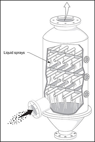
A spray tower is a gas-liquid contactor used to achieve mass and heat transfer between a continuous gas phase and a dispersed liquid phase. It consists of an empty cylindrical vessel made of steel or plastic, and nozzles that spray liquid into the vessel. The inlet gas stream usually enters at the bottom of the tower and moves upward, while the liquid is sprayed downward from one or more levels. This flow of inlet gas and liquid in opposite directions is called countercurrent flow.
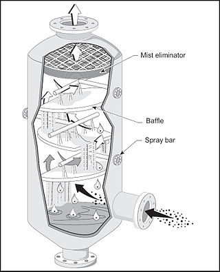
Baffle spray scrubbers are a technology for air pollution control. They are very similar to spray towers in design and operation. However, in addition to using the energy provided by the spray nozzles, baffles are added to allow the gas stream to atomize some liquid as it passes over them.
An important parameter in wet scrubbing systems is the rate of liquid flow. It is common in wet scrubber terminology to express the liquid flow as a function of the gas flow rate that is being treated. This is commonly called the liquid-to-gas ratio and uses the units of gallons per 1,000 actual cubic feet or litres per cubic metre (L/m3).
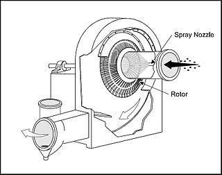
Mechanically aided scrubbers are a form of pollution control technology. This type of technology is a part of the group of air pollution controls collectively referred to as wet scrubbers.
The term wet scrubber describes a variety of devices that remove pollutants from a furnace flue gas or from other gas streams. In a wet scrubber, the polluted gas stream is brought into contact with the scrubbing liquid, by spraying it with the liquid, by forcing it through a pool of liquid, or by some other contact method, so as to remove the pollutants.
Cyclonic spray scrubbers are an air pollution control technology. They use the features of both the dry cyclone and the spray chamber to remove pollutants from gas streams.
A spray nozzle or atomizer is a device that facilitates the dispersion of a liquid by the formation of a spray. The production of a spray requires the fragmentation of liquid structures, such as liquid sheets or ligaments, into droplets, often by using kinetic energy to overcome the cost of creating additional surface area. A wide variety of spray nozzles exist, that make use of one or multiple liquid breakup mechanisms, which can be divided into three categories: liquid sheet breakup, jets and capillary waves. Spray nozzles are of great importance for many applications, where the spray nozzle is designed to have the right spray characteristics.
Particle collection in wet scrubbers capture relatively small dust particles with the wet scrubber's large liquid droplets. In most wet scrubbing systems, droplets produced are generally larger than 50 micrometres. As a point of reference, human hair ranges in diameter from 50 to 100 micrometres. The size distribution of particles to be collected is source specific. For example, particles produced by mechanical means tend to be large ; whereas, particles produced from combustion or a chemical reaction will have a substantial portion of small and submicrometre particles.
The term separator in oilfield terminology designates a pressure vessel used for separating well fluids produced from oil and gas wells into gaseous and liquid components. A separator for petroleum production is a large vessel designed to separate production fluids into their constituent components of oil, gas and water. A separating vessel may be referred to in the following ways: Oil and gas separator, Separator, Stage separator, Trap, Knockout vessel, Flash chamber, Expansion separator or expansion vessel, Scrubber, Filter. These separating vessels are normally used on a producing lease or platform near the wellhead, manifold, or tank battery to separate fluids produced from oil and gas wells into oil and gas or liquid and gas. An oil and gas separator generally includes the following essential components and features:
A vessel that includes (a) primary separation device and/or section, (b) secondary "gravity" settling (separating) section, (c) mist extractor to remove small liquid particles from the gas, (d) gas outlet, (e) liquid settling (separating) section to remove gas or vapor from oil, (f) oil outlet, and (g) water outlet.
Adequate volumetric liquid capacity to handle liquid surges (slugs) from the wells and/or flowlines.
Adequate vessel diameter and height or length to allow most of the liquid to separate from the gas so that the mist extractor will not be flooded.
A means of controlling an oil level in the separator, which usually includes a liquid-level controller and a diaphragm motor valve on the oil outlet.
A back pressure valve on the gas outlet to maintain a steady pressure in the vessel.
Pressure relief devices.
In chemical engineering, a vapor–liquid separator is a device used to separate a vapor–liquid mixture into its constituent phases. It can be a vertical or horizontal vessel, and can act as a 2-phase or 3-phase separator.
A spray is a dynamic collection of drops dispersed in a gas. The process of forming a spray is known as atomization. A spray nozzle is the device used to generate a spray. The two main uses of sprays are to distribute material over a cross-section and to generate liquid surface area. There are thousands of applications in which sprays allow material to be used most efficiently. The spray characteristics required must be understood in order to select the most appropriate technology, optimal device and size.
References
↑ Johnstone, H. F.; Roberts, M. N. (1949-11-01). "Deposition of Aerosol Particles from Moving Gas Streams". Industrial & Engineering Chemistry. 41 (11): 2417–2423. doi:10.1021/ie50479a019. ISSN0019-7866.
↑ Jones, William P. (1949-11-05). "Development of the Venturi Scrubber". Industrial & Engineering Chemistry. 41 (11): 2424–2427. doi:10.1021/ie50479a020. ISSN0019-7866.
1 2 Brady, J. D., and L. K. Legatski. 1977. Venturi scrubbers. In P. N. Cheremisinoff and R. A. Young (Eds.), Air Pollution Control and Design Handbook. Part 2. New York: Marcel Dekker.
1 2 Gilbert, J. W. 1977. Jet venturi fume scrubbing. In P. N. Cheremisinoff and R. A. Young (Eds.), Air Pollution Control and Design Handbook. Part 2. New York: Marcel Dekker.
Anderson 2000 Company. Venturi scrubbing equipment. Engineering Manual with Operating and Maintenance Instructions. Atlanta: Anderson Company.
Bethea, R. M. 1978. Air Pollution Control Technology. New York: Van Nostrand Reinhold.
Buonicore, A. J. 1982. Wet scrubbers. In L. Theodore and A. J. Buonicore (Eds.), Air Pollution Control Equipment, Design, Selection, Operation and Maintenance. Englewood Cliffs: Prentice-Hall.
Calvert, S. 1977. How to choose a particulate scrubber. Chemical Engineering. 84:133-140.
Johnstone, H. F., and M. H. Roberts. 1949. Deposition of aerosol particles from moving gas streams. Industrial and Engineering Chemistry. 41:2417-2423.
Kelly, J. W. 1978, December 4. Maintaining venturi-tray scrubbers. Chemical Engineering.
This page is based on this Wikipedia article Text is available under the CC BY-SA 4.0 license; additional terms may apply. Images, videos and audio are available under their respective licenses.