
An amplifier, electronic amplifier or (informally) amp is an electronic device that can increase the magnitude of a signal. It is a two-port electronic circuit that uses electric power from a power supply to increase the amplitude of a signal applied to its input terminals, producing a proportionally greater amplitude signal at its output. The amount of amplification provided by an amplifier is measured by its gain: the ratio of output voltage, current, or power to input. An amplifier is defined as a circuit that has a power gain greater than one.

A logic gate is a device that performs a Boolean function, a logical operation performed on one or more binary inputs that produces a single binary output. Depending on the context, the term may refer to an ideal logic gate, one that has, for instance, zero rise time and unlimited fan-out, or it may refer to a non-ideal physical device.

In electronics, a comparator is a device that compares two voltages or currents and outputs a digital signal indicating which is larger. It has two analog input terminals and and one binary digital output . The output is ideally
Transistor–transistor logic (TTL) is a logic family built from bipolar junction transistors. Its name signifies that transistors perform both the logic function and the amplifying function, as opposed to earlier resistor–transistor logic (RTL) and diode–transistor logic (DTL).
NMOS or nMOS logic uses n-type (-) MOSFETs to implement logic gates and other digital circuits.
In electronics, a multi-transistor configuration called the Darlington configuration is a circuit consisting of two bipolar transistors with the emitter of one transistor connected to the base of the other, such that the current amplified by the first transistor is amplified further by the second one. The collectors of both transistors are connected together. This configuration has a much higher current gain than each transistor taken separately. It acts like and is often packaged as a single transistor. It was invented in 1953 by Sidney Darlington.
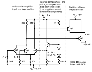
In electronics, emitter-coupled logic (ECL) is a high-speed integrated circuit bipolar transistor logic family. ECL uses an overdriven bipolar junction transistor (BJT) differential amplifier with single-ended input and limited emitter current to avoid the saturated region of operation and its slow turn-off behavior. As the current is steered between two legs of an emitter-coupled pair, ECL is sometimes called current-steering logic (CSL), current-mode logic (CML) or current-switch emitter-follower (CSEF) logic.

A differential amplifier is a type of electronic amplifier that amplifies the difference between two input voltages but suppresses any voltage common to the two inputs. It is an analog circuit with two inputs and and one output , in which the output is ideally proportional to the difference between the two voltages:
The Hartley oscillator is an electronic oscillator circuit in which the oscillation frequency is determined by a tuned circuit consisting of capacitors and inductors, that is, an LC oscillator. The circuit was invented in 1915 by American engineer Ralph Hartley. The distinguishing feature of the Hartley oscillator is that the tuned circuit consists of a single capacitor in parallel with two inductors in series, and the feedback signal needed for oscillation is taken from the center connection of the two inductors.

In electronics, a Schmitt trigger is a comparator circuit with hysteresis implemented by applying positive feedback to the noninverting input of a comparator or differential amplifier. It is an active circuit which converts an analog input signal to a digital output signal. The circuit is named a trigger because the output retains its value until the input changes sufficiently to trigger a change. In the non-inverting configuration, when the input is higher than a chosen threshold, the output is high. When the input is below a different (lower) chosen threshold the output is low, and when the input is between the two levels the output retains its value. This dual threshold action is called hysteresis and implies that the Schmitt trigger possesses memory and can act as a bistable multivibrator. There is a close relation between the two kinds of circuits: a Schmitt trigger can be converted into a latch and a latch can be converted into a Schmitt trigger.
Resistor–transistor logic (RTL), sometimes also known as transistor–resistor logic (TRL), is a class of digital circuits built using resistors as the input network and bipolar junction transistors (BJTs) as switching devices. RTL is the earliest class of transistorized digital logic circuit; it was succeeded by diode–transistor logic (DTL) and transistor–transistor logic (TTL).

Diode–transistor logic (DTL) is a class of digital circuits that is the direct ancestor of transistor–transistor logic. It is called so because the logic gating functions AND and OR are performed by diode logic, while logical inversion (NOT) and amplification is performed by a transistor.

In electronics, a buffer amplifier is a unity gain amplifier that copies a signal from one circuit to another while transforming its electrical impedance to provide a more ideal source. This "buffers" the signal source in the first circuit against being affected by currents from the electrical load of the second circuit and may simply be called a buffer or follower when context is clear.

A current source is an electronic circuit that delivers or absorbs an electric current which is independent of the voltage across it.

In electronic logic circuits, a pull-up resistor (PU) or pull-down resistor (PD) is a resistor used to ensure a known state for a signal. It is typically used in combination with components such as switches and transistors, which physically interrupt the connection of subsequent components to ground or to VCC. Closing the switch creates a direct connection to ground or VCC, but when the switch is open, the rest of the circuit would be left floating.
Diode logic constructs AND and OR logic gates with diodes and resistors.
Open collector, open drain, open emitter, and open source refer to integrated circuit (IC) output pin configurations that process the IC's internal function through a transistor with an exposed terminal that is internally unconnected. One of the IC's internal high or low voltage rails typically connects to another terminal of that transistor. When the transistor is off, the output is internally disconnected from any internal power rail, a state called "high-impedance" (Hi-Z). Open outputs configurations thus differ from push–pull outputs, which use a pair of transistors to output a specific voltage or current.
In electronics, high impedance means that a point in a circuit allows a relatively small amount of current through, per unit of applied voltage at that point. High impedance circuits are low current and potentially high voltage, whereas low impedance circuits are the opposite. Numerical definitions of "high impedance" vary by application.
In digital circuits, a logic level is one of a finite number of states that a digital signal can inhabit. Logic levels are usually represented by the voltage difference between the signal and ground, although other standards exist. The range of voltage levels that represent each state depends on the logic family being used. A logic-level shifter can be used to allow compatibility between different circuits.
An electronic circuit is composed of individual electronic components, such as resistors, transistors, capacitors, inductors and diodes, connected by conductive wires or traces through which electric current can flow. It is a type of electrical circuit. For a circuit to be referred to as electronic, rather than electrical, generally at least one active component must be present. The combination of components and wires allows various simple and complex operations to be performed: signals can be amplified, computations can be performed, and data can be moved from one place to another.


