
Amplitude modulation (AM) is a modulation technique used in electronic communication, most commonly for transmitting messages with a radio wave. In amplitude modulation, the amplitude of the wave is varied in proportion to that of the message signal, such as an audio signal. This technique contrasts with angle modulation, in which either the frequency of the carrier wave is varied, as in frequency modulation, or its phase, as in phase modulation.
In electronics and telecommunications, modulation is the process of varying one or more properties of a periodic waveform, called the carrier signal, with a separate signal called the modulation signal that typically contains information to be transmitted. For example, the modulation signal might be an audio signal representing sound from a microphone, a video signal representing moving images from a video camera, or a digital signal representing a sequence of binary digits, a bitstream from a computer.
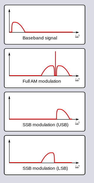
In radio communications, single-sideband modulation (SSB) or single-sideband suppressed-carrier modulation (SSB-SC) is a type of modulation used to transmit information, such as an audio signal, by radio waves. A refinement of amplitude modulation, it uses transmitter power and bandwidth more efficiently. Amplitude modulation produces an output signal the bandwidth of which is twice the maximum frequency of the original baseband signal. Single-sideband modulation avoids this bandwidth increase, and the power wasted on a carrier, at the cost of increased device complexity and more difficult tuning at the receiver.

In telecommunications and signal processing, baseband is the range of frequencies occupied by a signal that has not been modulated to higher frequencies. Baseband signals typically originate from transducers, converting some other variable into an electrical signal. For example, the electronic output of a microphone is a baseband signal that is analogous to the applied voice audio. In conventional analog radio broadcasting, the baseband audio signal is used to modulate an RF carrier signal of a much higher frequency.
A carrier system is a telecommunications system that transmits information, such as the voice signals of a telephone call and the video signals of television, by modulation of one or multiple carrier signals above the principal voice frequency or data rate.

In telecommunications and computer networking, multiplexing is a method by which multiple analog or digital signals are combined into one signal over a shared medium. The aim is to share a scarce resource – a physical transmission medium. For example, in telecommunications, several telephone calls may be carried using one wire. Multiplexing originated in telegraphy in the 1870s, and is now widely applied in communications. In telephony, George Owen Squier is credited with the development of telephone carrier multiplexing in 1910.

In telecommunications, a repeater is an electronic device that receives a signal and retransmits it. Repeaters are used to extend transmissions so that the signal can cover longer distances or be received on the other side of an obstruction. Some types of repeaters broadcast an identical signal, but alter its method of transmission, for example, on another frequency or baud rate.

The T-carrier is a member of the series of carrier systems developed by AT&T Bell Laboratories for digital transmission of multiplexed telephone calls.
Time-division multiplexing (TDM) is a method of transmitting and receiving independent signals over a common signal path by means of synchronized switches at each end of the transmission line so that each signal appears on the line only a fraction of time in an alternating pattern. It can be used when the bit rate of the transmission medium exceeds that of the signal to be transmitted. This form of signal multiplexing was developed in telecommunications for telegraphy systems in the late 19th century, but found its most common application in digital telephony in the second half of the 20th century.
In telecommunications, frequency-division multiplexing (FDM) is a technique by which the total bandwidth available in a communication medium is divided into a series of non-overlapping frequency bands, each of which is used to carry a separate signal. This allows a single transmission medium such as a microwave radio link, cable or optical fiber to be shared by multiple independent signals. Another use is to carry separate serial bits or segments of a higher rate signal in parallel.

In electronics, ring modulation is a signal processing function, an implementation of frequency mixing, in which two signals are combined to yield an output signal. One signal, called the carrier, is typically a sine wave or another simple waveform; the other signal is typically more complicated and is called the input or the modulator signal. A ring modulator is an electronic device for ring modulation. A ring modulator may be used in music synthesizers and as an effects unit.
This is an index of articles relating to electronics and electricity or natural electricity and things that run on electricity and things that use or conduct electricity.

A cellular network or mobile network is a telecommunications network where the link to and from end nodes is wireless and the network is distributed over land areas called cells, each served by at least one fixed-location transceiver. These base stations provide the cell with the network coverage which can be used for transmission of voice, data, and other types of content. A cell typically uses a different set of frequencies from neighboring cells, to avoid interference and provide guaranteed service quality within each cell.
In communications systems, robbed-bit signaling (RBS) is a scheme to provide maintenance and line signaling services on many T1 digital carrier circuits using channel-associated signaling (CAS). The T1 carrier circuit is a type of dedicated circuit currently employed in North America and Japan.
2600 hertz (2600 Hz) is a frequency in hertz that was used in telecommunication signaling in mid-20th century long-distance telephone networks using carrier systems.

E and M signaling is a type of supervisory line signaling that uses DC signals on separate leads, called the "E" lead and "M" lead, traditionally used in the telecommunications industry between telephone switches. Various mnemonic names have been used to memorize these letters, such as Ear and Mouth, the most common variation.
A duplex communication system is a point-to-point system composed of two or more connected parties or devices that can communicate with one another in both directions. Duplex systems are employed in many communications networks, either to allow for simultaneous communication in both directions between two connected parties or to provide a reverse path for the monitoring and remote adjustment of equipment in the field. There are two types of duplex communication systems: full-duplex (FDX) and half-duplex (HDX).

Microwave transmission is the transmission of information by electromagnetic waves with wavelengths in the microwave frequency range of 300 MHz to 300 GHz of the electromagnetic spectrum. Microwave signals are normally limited to the line of sight, so long-distance transmission using these signals requires a series of repeaters forming a microwave relay network. It is possible to use microwave signals in over-the-horizon communications using tropospheric scatter, but such systems are expensive and generally used only in specialist roles.
The L-carrier system was one of a series of carrier systems developed by AT&T for high-capacity transmission for long-distance communications. Over a period from the late 1930s to the 1970s, the system evolved in six significant phases of development, designated by Bell System engineers as L-1 through L-5, and L-5E. Coaxial cable was the principal transmission medium in all stages, initially lending the system another description i.e. the coaxial system. It was the successor to a series of previous carrier systems, typically identified by capital letters. In the 1960s, the system was hardened against the dangers of the Cold War using complete placement of all terminal and repeater equipment in hardened underground vaults.

A telephone exchange, also known as a telephone switch or central office, is a crucial component in the public switched telephone network (PSTN) or large enterprise telecommunications systems. It facilitates the interconnection of telephone subscriber lines or digital system virtual circuits, enabling telephone calls between subscribers.