Frequency-division multiplexing

Last updated

In telecommunications, frequency-division multiplexing (FDM) is a technique by which the total bandwidth available in a communication medium is divided into a series of non-overlapping frequency bands, each of which is used to carry a separate signal. This allows a single transmission medium such as a microwave radio link, cable or optical fiber to be shared by multiple independent signals. Another use is to carry separate serial bits or segments of a higher rate signal in parallel.

Contents

The most common example of frequency-division multiplexing is radio and television broadcasting, in which multiple radio signals at different frequencies pass through the air at the same time. Another example is cable television, in which many television channels are carried simultaneously on a single cable. FDM is also used by telephone systems to transmit multiple telephone calls through high capacity trunklines, communications satellites to transmit multiple channels of data on uplink and downlink radio beams, and broadband DSL modems to transmit large amounts of computer data through twisted pair telephone lines, among many other uses.

An analogous technique called wavelength division multiplexing is used in fiber-optic communication, in which multiple channels of data are transmitted over a single optical fiber using different wavelengths (frequencies).

Principle

The passband of an FDM channel carrying digital data, modulated by QPSK quadrature phase-shift keying. Screenshot-fdm-75-random-am.png
The passband of an FDM channel carrying digital data, modulated by QPSK quadrature phase-shift keying.

The multiple separate information (modulation) signals that are sent over an FDM system, such as the video signals of the television channels that are sent over a cable TV system, are called baseband signals. At the source end, for each frequency channel, an electronic oscillator generates a carrier signal, a steady oscillating waveform at a single frequency that serves to "carry" information. The carrier is much higher in frequency than the baseband signal. The carrier signal and the baseband signal are combined in a modulator circuit. The modulator alters some aspect of the carrier signal, such as its amplitude, frequency, or phase, with the baseband signal, "piggybacking" the data onto the carrier.

The result of modulating (mixing) the carrier with the baseband signal is to generate sub-frequencies near the carrier frequency, at the sum (fC + fB) and difference (fCfB) of the frequencies. The information from the modulated signal is carried in sidebands on each side of the carrier frequency. Therefore, all the information carried by the channel is in a narrow band of frequencies clustered around the carrier frequency, this is called the passband of the channel.

Similarly, additional baseband signals are used to modulate carriers at other frequencies, creating other channels of information. The carriers are spaced far enough apart in frequency that the band of frequencies occupied by each channel, the passbands of the separate channels, do not overlap. All the channels are sent through the transmission medium, such as a coaxial cable, optical fiber, or through the air using a radio transmitter. As long as the channel frequencies are spaced far enough apart that none of the passbands overlap, the separate channels will not interfere with each other. Thus the available bandwidth is divided into "slots" or channels, each of which can carry a separate modulated signal.

For example, the coaxial cable used by cable television systems has a bandwidth of about 1000 MHz, but the passband of each television channel is only 6 MHz wide, so there is room for many channels on the cable (in modern digital cable systems each channel in turn is subdivided into subchannels and can carry up to 10 digital television channels).

At the destination end of the cable or fiber, or the radio receiver, for each channel a local oscillator produces a signal at the carrier frequency of that channel, that is mixed with the incoming modulated signal. The frequencies subtract, producing the baseband signal for that channel again. This is called demodulation. The resulting baseband signal is filtered out of the other frequencies and output to the user.

Telephone

For long distance telephone connections, 20th century telephone companies used L-carrier and similar coaxial cable systems carrying thousands of voice circuits multiplexed in multiple stages by channel banks.

For shorter distances, cheaper balanced pair cables were used for various systems including Bell System K- and N-Carrier. Those cables did not allow such large bandwidths, so only 12 voice channels (double sideband) and later 24 (single sideband) were multiplexed into four wires, one pair for each direction with repeaters every several miles, approximately 10 km. See 12-channel carrier system. By the end of the 20th century, FDM voice circuits had become rare. Modern telephone systems employ digital transmission, in which time-division multiplexing (TDM) is used instead of FDM.

Since the late 20th century, digital subscriber lines (DSL) have used a Discrete multitone (DMT) system to divide their spectrum into frequency channels.

Group and supergroup

A once commonplace FDM system, used for example in L-carrier, uses crystal filters which operate at the 8 MHz range to form a Channel Group of 12 channels, 48 kHz bandwidth in the range 8140 to 8188 kHz by selecting carriers in the range 8140 to 8184 kHz selecting upper sideband this group can then be translated to the standard range 60 to 108 kHz by a carrier of 8248 kHz. Such systems are used in DTL (Direct To Line) and DFSG (Directly formed super group).

132 voice channels (2SG + 1G) can be formed using DTL plane the modulation and frequency plan are given in FIG1 and FIG2 use of DTL technique allows the formation of a maximum of 132 voice channels that can be placed direct to line. DTL eliminates group and super group equipment.

DFSG can take similar steps where a direct formation of a number of super groups can be obtained in the 8 kHz the DFSG also eliminates group equipment and can offer:

Both DTL and DFSG can fit the requirement of low density system (using DTL) and higher density system (using DFSG). The DFSG terminal is similar to DTL terminal except instead of two super groups many super groups are combined. A Mastergroup of 600 channels (10 super-groups) is an example based on DFSG.

Other examples

FDM can also be used to combine signals before final modulation onto a carrier wave. In this case the carrier signals are referred to as subcarriers: an example is stereo FM transmission, where a 38 kHz subcarrier is used to separate the left-right difference signal from the central left-right sum channel, prior to the frequency modulation of the composite signal. An analog NTSC television channel is divided into subcarrier frequencies for video, color, and audio. DSL uses different frequencies for voice and for upstream and downstream data transmission on the same conductors, which is also an example of frequency duplex.

Where frequency-division multiplexing is used as to allow multiple users to share a physical communications channel, it is called frequency-division multiple access (FDMA). [1]

FDMA is the traditional way of separating radio signals from different transmitters.

In the 1860s and 70s, several inventors attempted FDM under the names of acoustic telegraphy and harmonic telegraphy. Practical FDM was only achieved in the electronic age. Meanwhile, their efforts led to an elementary understanding of electroacoustic technology, resulting in the invention of the telephone.

See also

Related Research Articles

<span class="mw-page-title-main">Amplitude modulation</span> Radio modulation via wave amplitude

Amplitude modulation (AM) is a modulation technique used in electronic communication, most commonly for transmitting messages with a radio wave. In amplitude modulation, the amplitude of the wave is varied in proportion to that of the message signal, such as an audio signal. This technique contrasts with angle modulation, in which either the frequency of the carrier wave is varied, as in frequency modulation, or its phase, as in phase modulation.

<span class="mw-page-title-main">Bandwidth (signal processing)</span> Range of usable frequencies

Bandwidth is the difference between the upper and lower frequencies in a continuous band of frequencies. It is typically measured in unit of hertz.

In electronics and telecommunications, modulation is the process of varying one or more properties of a periodic waveform, called the carrier signal, with a separate signal called the modulation signal that typically contains information to be transmitted. For example, the modulation signal might be an audio signal representing sound from a microphone, a video signal representing moving images from a video camera, or a digital signal representing a sequence of binary digits, a bitstream from a computer.

<span class="mw-page-title-main">Orthogonal frequency-division multiplexing</span> Method of encoding digital data on multiple carrier frequencies

In telecommunications, orthogonal frequency-division multiplexing (OFDM) is a type of digital transmission used in digital modulation for encoding digital (binary) data on multiple carrier frequencies. OFDM has developed into a popular scheme for wideband digital communication, used in applications such as digital television and audio broadcasting, DSL internet access, wireless networks, power line networks, and 4G/5G mobile communications.

<span class="mw-page-title-main">Single-sideband modulation</span> Type of modulation

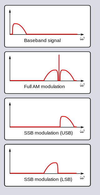
In radio communications, single-sideband modulation (SSB) or single-sideband suppressed-carrier modulation (SSB-SC) is a type of modulation used to transmit information, such as an audio signal, by radio waves. A refinement of amplitude modulation, it uses transmitter power and bandwidth more efficiently. Amplitude modulation produces an output signal the bandwidth of which is twice the maximum frequency of the original baseband signal. Single-sideband modulation avoids this bandwidth increase, and the power wasted on a carrier, at the cost of increased device complexity and more difficult tuning at the receiver.

<span class="mw-page-title-main">Baseband</span> Range of frequencies occupied by an unmodulated signal

In telecommunications and signal processing, baseband is the range of frequencies occupied by a signal that has not been modulated to higher frequencies. Baseband signals typically originate from transducers, converting some other variable into an electrical signal. For example, the electronic output of a microphone is a baseband signal that is analogous to the applied voice audio. In conventional analog radio broadcasting, the baseband audio signal is used to modulate an RF carrier signal of a much higher frequency.

A carrier system is a telecommunications system that transmits information, such as the voice signals of a telephone call and the video signals of television, by modulation of one or multiple carrier signals above the principal voice frequency or data rate.

<span class="mw-page-title-main">Multiplexing</span> Method of combining multiple signals into one signal over a shared medium

In telecommunications and computer networking, multiplexing is a method by which multiple analog or digital signals are combined into one signal over a shared medium. The aim is to share a scarce resource – a physical transmission medium. For example, in telecommunications, several telephone calls may be carried using one wire. Multiplexing originated in telegraphy in the 1870s, and is now widely applied in communications. In telephony, George Owen Squier is credited with the development of telephone carrier multiplexing in 1910.

<span class="mw-page-title-main">Sideband</span> Radio communications concept

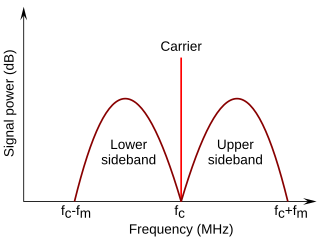
In radio communications, a sideband is a band of frequencies higher than or lower than the carrier frequency, that are the result of the modulation process. The sidebands carry the information transmitted by the radio signal. The sidebands comprise all the spectral components of the modulated signal except the carrier. The signal components above the carrier frequency constitute the upper sideband (USB), and those below the carrier frequency constitute the lower sideband (LSB). All forms of modulation produce sidebands.

Data communication or digital communications, including data transmission and data reception, is the transfer and reception of data in the form of a digital bitstream or a digitized analog signal transmitted over a point-to-point or point-to-multipoint communication channel. Examples of such channels are copper wires, optical fibers, wireless communication using radio spectrum, storage media and computer buses. The data are represented as an electromagnetic signal, such as an electrical voltage, radiowave, microwave, or infrared signal.

<span class="mw-page-title-main">Composite video</span> Analog video signal format

Composite video is an analog video format that typically carries a 525 or 625 line signal on a single channel, unlike the higher-quality S-Video and the even higher-quality component video.

<span class="mw-page-title-main">Carrier wave</span> Waveform that is modulated with a signal to convey information

In telecommunications, a carrier wave, carrier signal, or just carrier, is a waveform that is modulated (modified) with an information-bearing signal for the purpose of conveying information.

A subcarrier is a sideband of a radio frequency carrier wave, which is modulated to send additional information. Examples include the provision of colour in a black and white television system or the provision of stereo in a monophonic radio broadcast. There is no physical difference between a carrier and a subcarrier; the "sub" implies that it has been derived from a carrier, which has been amplitude modulated by a steady signal and has a constant frequency relation to it.

In telecommunications, a pilot signal is a signal, usually a single frequency, transmitted over a communications system for supervisory, control, equalization, continuity, synchronization, or reference purposes.

ANSI T1.413 is a technical standard that defines the requirements for the single asymmetric digital subscriber line (ADSL) for the interface between the telecommunications network and the customer installation in terms of their interaction and electrical characteristics. ADSL allows the provision of voiceband services including plain old telephone service (POTS) and data services up to 56 kbit/s, and a variety of digital channels. In the direction from the network to the customer premises (downstream), the digital bearer channels may consist of full-duplex low-speed bearer channels and simpler high-speed bearer channels; in the other (upstream) direction, only low-speed bearer channels are provided.

Spectral efficiency, spectrum efficiency or bandwidth efficiency refers to the information rate that can be transmitted over a given bandwidth in a specific communication system. It is a measure of how efficiently a limited frequency spectrum is utilized by the physical layer protocol, and sometimes by the medium access control.

In a digitally modulated signal or a line code, symbol rate, modulation rate or baud rate is the number of symbol changes, waveform changes, or signaling events across the transmission medium per unit of time. The symbol rate is measured in baud (Bd) or symbols per second. In the case of a line code, the symbol rate is the pulse rate in pulses per second. Each symbol can represent or convey one or several bits of data. The symbol rate is related to the gross bit rate, expressed in bits per second.

Subcarrier Multiplexing (SCM) is a method for combining (multiplexing) many different communications signals so that they can be transmitted along a single optical fiber. SCM (also known as SCMA, SubCarrier Multiple Access) is used in passive optical network (PON) access infrastructures as a variant of wavelength division multiplexing (WDM).

CCIR System A was the 405-line analog broadcast television system adopted in the UK and Ireland. System A service started in 1936 and was discontinued in 1985.

Non-orthogonal frequency-division multiplexing (N-OFDM) is a method of encoding digital data on multiple carrier frequencies with non-orthogonal intervals between frequency of sub-carriers. N-OFDM signals can be used in communication and radar systems.

References

  1. White, Curt (2007). Data Communications and Computer Networks . Boston, MA: Thomson Course Technology. pp.  140–143. ISBN   978-1-4188-3610-8.
General