The term WDM is commonly applied to an optical carrier, which is typically described by its wavelength, whereas frequency-division multiplexing typically applies to a radio carrier, more often described by frequency.[2] This is purely conventional because wavelength and frequency communicate the same information. Specifically, frequency (in Hertz, which is cycles per second) multiplied by wavelength (the physical length of one cycle) equals velocity of the carrier wave. In a vacuum, this is the speed of light (usually denoted by the lowercase letter, c). In glass fiber, velocity is substantially slower - usually about 0.7 times c. The data rate in practical systems is a fraction of the carrier frequency.
Systems
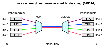
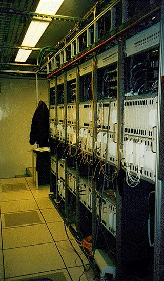
WDM operating principleWDM System in rack 19/21''
A WDM system uses a multiplexer at the transmitter to join the several signals together and a demultiplexer at the receiver to split them apart.[1] With the right type of fiber, it is possible to have a device that does both simultaneously and can function as an optical add-drop multiplexer. The optical filtering devices used have conventionally been etalons (stable solid-state single-frequency Fabry–Pérot interferometers in the form of thin-film-coated optical glass). As there are three different WDM types, whereof one is called WDM, the notation xWDM is normally used when discussing the technology as such.[3]
The concept was first published in 1970 by Delange,[4] and by 1980 WDM systems were being realized in the laboratory. The first WDM systems combined only two signals. Modern systems can handle 160 signals and can thus expand a basic 100Gbit/s system over a single fiber pair to over 16Tbit/s. A system of 320 channels is also present (12.5GHz channel spacing, see below.)
WDM systems are popular with telecommunications companies because they allow them to expand the capacity of the network without laying more fiber. By using WDM and optical amplifiers, they can accommodate several generations of technology development in their optical infrastructure without having to overhaul the backbone network. The capacity of a given link can be expanded simply by upgrading the multiplexers and demultiplexers at each end.
This is often done by the use of optical-to-electrical-to-optical (O/E/O) translation at the very edge of the transport network, thus permitting interoperation with existing equipment with optical interfaces.[3]
Most WDM systems operate on single-mode fiber optical cables which have a core diameter of 9μm. Certain forms of WDM can also be used in multi-mode fiber cables (also known as premises cables) which have core diameters of 50 or 62.5μm.
Early WDM systems were expensive and complicated to run. However, recent standardization and a better understanding of the dynamics of WDM systems have made WDM less expensive to deploy.
Optical receivers, in contrast to laser sources, tend to be wideband devices. Therefore, the demultiplexer must provide the wavelength selectivity of the receiver in the WDM system.
WDM systems are divided into three different wavelength patterns: normal (WDM), coarse (CWDM) and dense (DWDM). Normal WDM (sometimes called BWDM) uses the two normal wavelengths 1310 and 1550nm on one fiber. Coarse WDM provides up to 16 channels across multiple transmission windows of silica fibers. Dense WDM (DWDM) uses the C-Band (1530nm-1565nm) transmission window but with denser channel spacing. Channel plans vary, but a typical DWDM system would use 40 channels at 100GHz spacing or 80 channels with 50GHz spacing. Some technologies are capable of 12.5GHz spacing (sometimes called ultra-dense WDM). New amplification options (Raman amplification) enable the extension of the usable wavelengths to the L-band (1565–1625nm), more or less doubling these numbers.
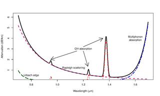
Coarse wavelength-division multiplexing (CWDM), in contrast to DWDM, uses increased channel spacing to allow less sophisticated and thus cheaper transceiver designs. To provide 16 channels on a single fiber, CWDM uses the entire frequency band spanning the second and third transmission windows (1310/1550nm respectively) including the critical frequencies where OH scattering may occur. OH-free silica fibers are recommended if the wavelengths between the second and third transmission windows are to be used[citation needed]. Avoiding this region, the channels 47, 49, 51, 53, 55, 57, 59, 61 remain and these are the most commonly used. With OS2 fibers the water peak problem is overcome, and all possible 18 channels can be used.
WDM, CWDM and DWDM are based on the same concept of using multiple wavelengths of light on a single fiber but differ in the spacing of the wavelengths, number of channels, and the ability to amplify the multiplexed signals in the optical space. EDFA provide an efficient wideband amplification for the C-band, Raman amplification adds a mechanism for amplification in the L-band. For CWDM, wideband optical amplification is not available, limiting the optical spans to several tens of kilometers.
Coarse WDM
Series of SFP+ transceivers for 10Gbit/s WDM communications
Originally, the term coarse wavelength-division multiplexing (CWDM) was fairly generic and described a number of different channel configurations. In general, the choice of channel spacings and frequency in these configurations precluded the use of erbium doped fiber amplifiers (EDFAs). Prior to the relatively recent ITU standardization of the term, one common definition for CWDM was two or more signals multiplexed onto a single fiber, with one signal in the 1550nm band and the other in the 1310nm band.
In 2002, the ITU standardized a channel spacing grid for CWDM (ITU-T G.694.2) using the wavelengths from 1270nm through 1610nm with a channel spacing of 20nm. ITU G.694.2 was revised in 2003 to shift the channel centers by 1nm so, strictly speaking, the center wavelengths are 1271 to 1611nm.[5] Many CWDM wavelengths below 1470nm are considered unusable on older G.652 specification fibers, due to the increased attenuation in the 1270–1470nm bands. Newer fibers which conform to the G.652.C and G.652.D[6] standards, such as Corning SMF-28e and Samsung Widepass, nearly eliminate the water-related attenuation peak at 1383nm and allow for full operation of all 18 ITU CWDM channels in metropolitan networks.
The main characteristic of the recent ITU CWDM standard is that the signals are not spaced appropriately for amplification by EDFAs. This limits the total CWDM optical span to somewhere near 60km for a 2.5Gbit/s signal, which is suitable for use in metropolitan applications. The relaxed optical frequency stabilization requirements allow the associated costs of CWDM to approach those of non-WDM optical components.
CWDM Applications
CWDM is being used in cable television networks, where different wavelengths are used for the downstream and upstream signals. In these systems, the wavelengths used are often widely separated. For example, the downstream signal might be at 1310nm while the upstream signal is at 1550nm.[citation needed]
The 10GBASE-LX4 10Gbit/s physical layer standard is an example of a CWDM system in which four wavelengths near 1310nm, each carrying a 3.125gigabit-per-second (Gbit/s) data stream, are used to carry 10Gbit/s of aggregate data.[7]
Passive CWDM is an implementation of CWDM that uses no electrical power. It separates the wavelengths using passive optical components such as bandpass filters and prisms. Many manufacturers are promoting passive CWDM to deploy fiber to the home.[citation needed]
Dense WDM
Dense wavelength-division multiplexing (DWDM) refers originally to optical signals multiplexed within the 1550nm band so as to leverage the capabilities (and cost) of erbium doped fiber amplifiers (EDFAs), which are effective for wavelengths between approximately 1525–1565nm (C band), or 1570–1610nm (L band). EDFAs were originally developed to replace SONET/SDH optical-electrical-optical (OEO) regenerators, which they have made practically obsolete. EDFAs can amplify any optical signal in their operating range, regardless of the modulated bit rate. In terms of multi-wavelength signals, so long as the EDFA has enough pump energy available to it, it can amplify as many optical signals as can be multiplexed into its amplification band (though signal densities are limited by choice of modulation format). EDFAs therefore allow a single-channel optical link to be upgraded in bit rate by replacing only equipment at the ends of the link, while retaining the existing EDFA or series of EDFAs through a long haul route. Furthermore, single-wavelength links using EDFAs can similarly be upgraded to WDM links at reasonable cost. The EDFA's cost is thus leveraged across as many channels as can be multiplexed into the 1550nm band.
DWDM systems
At this stage, a basic DWDM system contains several main components:
WDM multiplexer for DWDM communications
A DWDM terminal multiplexer. The terminal multiplexer contains a wavelength-converting transponder for each data signal, an optical multiplexer and where necessary an optical amplifier (EDFA). Each wavelength-converting transponder receives an optical data signal from the client layer, such as Synchronous optical networking [SONET /SDH] or another type of data signal, converts this signal into the electrical domain and re-transmits the signal at a specific wavelength using a 1,550nm band laser. These data signals are then combined into a multi-wavelength optical signal using an optical multiplexer, for transmission over a single fiber (e.g., SMF-28 fiber). The terminal multiplexer may or may not also include a local transmit EDFA for power amplification of the multi-wavelength optical signal. In the mid-1990s DWDM systems contained 4 or 8 wavelength-converting transponders; by 2000 or so, commercial systems capable of carrying 128 signals were available.
An intermediate line repeater is placed approximately every 80–100km to compensate for the loss of optical power as the signal travels along the fiber. The 'multi-wavelength optical signal' is amplified by an EDFA, which usually consists of several amplifier stages.
An intermediate optical terminal, or optical add-drop multiplexer. This is a remote amplification site that amplifies the multi-wavelength signal that may have traversed up to 140km or more before reaching the remote site. Optical diagnostics and telemetry are often extracted or inserted at such a site, to allow for localization of any fiber breaks or signal impairments. In more sophisticated systems (which are no longer point-to-point), several signals out of the multi-wavelength optical signal may be removed and dropped locally.
A DWDM terminal demultiplexer. At the remote site, the terminal de-multiplexer consisting of an optical de-multiplexer and one or more wavelength-converting transponders separates the multi-wavelength optical signal back into individual data signals and outputs them on separate fibers for client-layer systems (such as SONET/SDH). Originally, this de-multiplexing was performed entirely passively, except for some telemetry, as most SONET systems can receive 1,550nm signals. However, in order to allow for transmission to remote client-layer systems (and to allow for digital domain signal integrity determination) such de-multiplexed signals are usually sent to O/E/O output transponders prior to being relayed to their client-layer systems. Often, the functionality of output transponder has been integrated into that of input transponder, so that most commercial systems have transponders that support bi-directional interfaces on both their 1,550nm (i.e., internal) side, and external (i.e., client-facing) side. Transponders in some systems supporting 40GHz nominal operation may also perform forward error correction (FEC) via digital wrapper technology, as described in the ITU-TG.709 standard.
Optical Supervisory Channel (OSC). This is data channel that uses an additional wavelength usually outside the EDFA amplification band (at 1,510nm, 1,620nm, 1,310nm or another proprietary wavelength). The OSC carries information about the multi-wavelength optical signal as well as remote conditions at the optical terminal or EDFA site. It is also normally used for remote software upgrades and user (i.e., network operator) Network Management information. It is the multi-wavelength analog to SONET's DCC (or supervisory channel). ITU standards suggest that the OSC should utilize an OC-3 signal structure, though some vendors have opted to use Fast Ethernet or another signal format. Unlike the 1550nm multi-wavelength signal containing client data, the OSC is always terminated at intermediate amplifier sites, where it receives local information before re-transmission.
The introduction of the ITU-T G.694.1[8]frequency grid in 2002 has made it easier to integrate WDM with older but more standard SONET/SDH systems. WDM wavelengths are positioned in a grid having exactly 100GHz (about 0.8nm) spacing in optical frequency, with a reference frequency fixed at 193.10THz (1,552.52nm).[9] The main grid is placed inside the optical fiber amplifier bandwidth, but can be extended to wider bandwidths. The first commercial deployment of DWDM was made by Ciena Corporation on the Sprint network in June 1996.[10][11][12] Today's DWDM systems use 50GHz or even 25GHz channel spacing for up to 160 channel operation.[needs update][13]
DWDM systems have to maintain more stable wavelength or frequency than those needed for CWDM because of the closer spacing of the wavelengths. Precision temperature control of the laser transmitter is required in DWDM systems to prevent drift off a very narrow frequency window of the order of a few GHz. In addition, since DWDM provides greater maximum capacity it tends to be used at a higher level in the communications hierarchy than CWDM, for example on the Internet backbone and is therefore associated with higher modulation rates, thus creating a smaller market for DWDM devices with very high performance. These factors of smaller volume and higher performance result in DWDM systems typically being more expensive than CWDM.
Recent innovations in DWDM transport systems include pluggable and software-tunable transceiver modules capable of operating on 40 or 80 channels. This dramatically reduces the need for discrete spare pluggable modules, when a handful of pluggable devices can handle the full range of wavelengths.
Wavelength-converting transponders originally translated the transmit wavelength of a client-layer signal into one of the DWDM system's internal wavelengths in the 1,550nm band. Note that even external wavelengths in the 1,550nm will most likely need to be translated, as they will almost certainly not have the required frequency stability tolerances nor will it have the optical power necessary for the system's EDFA.
In the mid-1990s, however, wavelength-converting transponders rapidly took on the additional function of signal regeneration. Signal regeneration in transponders quickly evolved through 1R to 2R to 3R and into overhead-monitoring multi-bitrate 3R regenerators. These differences are outlined below:
1R
Retransmission. Basically, early transponders were garbage in, garbage out in that their output was nearly an analog copy of the received optical signal, with little signal cleanup occurring. This limited the reach of early DWDM systems because the signal had to be handed off to a client-layer receiver (likely from a different vendor) before the signal deteriorated too far. Signal monitoring was basically confined to optical domain parameters such as received power.
2R
Re-time and re-transmit. Transponders of this type were not very common and utilized a quasi-digital Schmitt-triggering method for signal clean-up. Some rudimentary signal-quality monitoring was done by such transmitters that basically looked at analogue parameters.
3R
Re-time, re-transmit, re-shape. 3R Transponders were fully digital and normally able to view SONET/SDH section layer overhead bytes such as A1 and A2 to determine signal quality health. Many systems will offer 2.5Gbit/s transponders, which will normally mean the transponder is able to perform 3R regeneration on OC-3/12/48 signals, and possibly gigabit Ethernet, and reporting on signal health by monitoring SONET/SDH section layer overhead bytes. Many transponders will be able to perform full multi-rate 3R in both directions. Some vendors offer 10Gbit/s transponders, which will perform Section layer overhead monitoring to all rates up to and including OC-192.
Muxponder
The muxponder (from multiplexed transponder) has different names depending on vendor. It essentially performs some relatively simple time-division multiplexing of lower-rate signals into a higher-rate carrier within the system (a common example is the ability to accept 4 OC-48s and then output a single OC-192 in the 1,550nm band). More recent muxponder designs have absorbed more and more TDM functionality, in some cases obviating the need for traditional SONET/SDH transport equipment.
As mentioned above, intermediate optical amplification sites in DWDM systems may allow for the dropping and adding of certain wavelength channels. In most systems deployed as of August 2006 this is done infrequently, because adding or dropping wavelengths requires manually inserting or replacing wavelength-selective cards. This is costly, and in some systems requires that all active traffic be removed from the DWDM system, because inserting or removing the wavelength-specific cards interrupts the multi-wavelength optical signal.
With a ROADM, network operators can remotely reconfigure the multiplexer by sending soft commands. The architecture of the ROADM is such that dropping or adding wavelengths does not interrupt the pass-through channels. Numerous technological approaches are utilized for various commercial ROADMs, the tradeoff being between cost, optical power, and flexibility.
This section needs expansion. You can help by adding to it. (June 2008)
When the network topology is a mesh, where nodes are interconnected by fibers to form an arbitrary graph, an additional fiber interconnection device is needed to route the signals from an input port to the desired output port. These devices are called optical crossconnectors (OXCs). Various categories of OXCs include electronic ("opaque"), optical ("transparent"), and wavelength-selective devices.
Enhanced WDM
Cisco's Enhanced WDM system is a network architecture that combines two different types of multiplexing technologies to transmit data over optical fibers.
EWDM combines 1Gbit/s Coarse Wave Division Multiplexing (CWDM) connections using SFPs and GBICs with 10Gbit/s Dense Wave Division Multiplexing (DWDM) connections using XENPAK, X2 or XFP DWDM modules. The Enhanced WDM system can use either passive or boosted DWDM connections to allow a longer range for the connection. In addition to this, C form-factor pluggable modules deliver 100Gbit/s Ethernet suitable for high-speed Internet backbone connections.
Shortwave WDM
Shortwave WDM uses vertical-cavity surface-emitting laser (VCSEL) transceivers with four wavelengths in the 846 to 953nm range over single OM5 fiber, or two-fiber connectivity for OM3/OM4 fiber.[7]
Transceivers versus transponders
Transceivers
Since communication over a single wavelength is one-way (simplex communication), and most practical communication systems require two-way (duplex communication) communication, two wavelengths will be required if on the same fiber; if separate fibers are used in a so-called fiber pair, then the same wavelength is normally used and it is not WDM. As a result, at each end both a transmitter and a receiver will be required. A combination of a transmitter and a receiver is called a transceiver; it converts an electrical signal to and from an optical signal. WDM transceivers made for single-strand operation require the opposing transmitters to use different wavelengths. WDM transceivers additionally require an optical splitter/combiner to couple the transmitter and receiver paths onto the one fiber strand.
Dense WDM (DWDM) Transceivers: Channel 17 to Channel 61 according to ITU-T.
Transponder
In practice, the signal inputs and outputs will not be electrical but optical instead (typically at 1550nm). This means that in effect wavelength converters are needed instead, which is exactly what a transponder is. A transponder can be made up of two transceivers placed after each other: the first transceiver converting the 1550nm optical signal to/from an electrical signal, and the second transceiver converting the electrical signal to/from an optical signal at the required wavelength. Transponders that don't use an intermediate electrical signal (all-optical transponders) are in development.
Synchronous Optical Networking (SONET) and Synchronous Digital Hierarchy (SDH) are standardized protocols that transfer multiple digital bit streams synchronously over optical fiber using lasers or highly coherent light from light-emitting diodes (LEDs). At low transmission rates data can also be transferred via an electrical interface. The method was developed to replace the plesiochronous digital hierarchy (PDH) system for transporting large amounts of telephone calls and data traffic over the same fiber without the problems of synchronization.
An optical amplifier is a device that amplifies an optical signal directly, without the need to first convert it to an electrical signal. An optical amplifier may be thought of as a laser without an optical cavity, or one in which feedback from the cavity is suppressed. Optical amplifiers are important in optical communication and laser physics. They are used as optical repeaters in the long distance fiber-optic cables which carry much of the world's telecommunication links.
In telecommunications, a transponder is a device that, upon receiving a signal, emits a different signal in response. The term is a blend of transmitter and responder.
Small Form-factor Pluggable (SFP) is a compact, hot-pluggable network interface module format used for both telecommunication and data communications applications. An SFP interface on networking hardware is a modular slot for a media-specific transceiver, such as for a fiber-optic cable or a copper cable. The advantage of using SFPs compared to fixed interfaces is that individual ports can be equipped with different types of transceivers as required, with the majority including optical line terminals, network cards, switches and routers.
A passive optical network (PON) is a fiber-optic telecommunications technology for delivering broadband network access to end-customers. Its architecture implements a point-to-multipoint topology in which a single optical fiber serves multiple endpoints by using unpowered (passive) fiber-optic splitters to divide the fiber bandwidth among the endpoints. Passive optical networks are often referred to as the last mile between an Internet service provider (ISP) and its customers. Many fiber ISPs prefer this technology.
An add-drop multiplexer (ADM) is an important element of an optical fiber network. A multiplexer combines, or multiplexes, several lower-bandwidth streams of data into a single beam of light. An add-drop multiplexer also has the capability to add one or more lower-bandwidth signals to an existing high-bandwidth data stream, and at the same time can extract or drop other low-bandwidth signals, removing them from the stream and redirecting them to some other network path. This is used as a local "on-ramp" and "off-ramp" to the high-speed network.
For telecommunications, a frequency grid is a table of all the central frequencies of channels allowed in a communications system.
In fiber optics, a reconfigurable optical add-drop multiplexer (ROADM) is a form of optical add-drop multiplexer that adds the ability to remotely switch traffic from a wavelength-division multiplexing (WDM) system at the wavelength layer. This is achieved through the use of a wavelength selective switching module. This allows individual or multiple wavelengths carrying data channels to be added and/or dropped from a transport fiber without the need to convert the signals on all of the WDM channels to electronic signals and back again to optical signals.
Optical networking is a means of communication that uses signals encoded in light to transmit information in various types of telecommunications networks. These include limited range local-area networks (LAN) or wide area networks (WANs), which cross metropolitan and regional areas as well as long-distance national, international and transoceanic networks. It is a form of optical communication that relies on optical amplifiers, lasers or LEDs and wavelength-division multiplexing (WDM) to transmit large quantities of data, generally across fiber-optic cables. Because it is capable of achieving extremely high bandwidth, it is an enabling technology for the Internet and telecommunication networks that transmit the vast majority of all human and machine-to-machine information.
An optical add-drop multiplexer (OADM) is a device used in wavelength-division multiplexing (WDM) systems for multiplexing and routing different channels of light into or out of a single-mode fiber (SMF). This is a type of optical node, which is generally used for the formation and the construction of optical telecommunications networks. "Add" and "drop" here refer to the capability of the device to add one or more new wavelength channels to an existing multi-wavelength WDM signal, and/or to drop (remove) one or more channels, passing those signals to another network path. An OADM may be considered to be a specific type of optical cross-connect.
ITU-T Recommendation G.709Interfaces for the Optical Transport Network (OTN) describes a means of communicating data over an optical network. It is a standardized method for transparent transport of services over optical wavelengths in DWDM systems. It is also known as Optical Transport Hierarchy (OTH) standard. The first edition of this protocol was approved in 2001.
An optical transport network (OTN) is a digital wrapper that encapsulates frames of data, to allow multiple data sources to be sent on the same channel. This creates an optical virtual private network for each client signal.
Fiber-optic communication is a method of transmitting information from one place to another by sending pulses of infrared or visible light through an optical fiber. The light is a form of carrier wave that is modulated to carry information. Fiber is preferred over electrical cabling when high bandwidth, long distance, or immunity to electromagnetic interference is required. This type of communication can transmit voice, video, and telemetry through local area networks or across long distances.
An optical interleaver is a 3-port passive fiber-optic device that is used to combine (Mux) two sets of dense wavelength-division multiplexing (DWDM) channels into a composite signal stream in an interleaving way. For example, optical interleaver takes two multiplexed signals with 100 GHz spacing and interleaves them, creating a denser DWDM signal with channels spaced 50 GHz apart. The process can be repeated, creating even denser composite signals with 25 GHz or 12.5 GHz spacing.
Wavelength selective switching components are used in WDM optical communications networks to route (switch) signals between optical fibres on a per-wavelength basis.
The STM-4 is a SDH ITU-T fiber optic network transmission standard. It has a bit rate of 622.080 Mbit/s.
IP over DWDM (IPoDWDM) is a technology used in telecommunications networks to integrate IP routers and network switches in the OTN . A true IPoDWDM solution is implemented only when the IP Routers and Switches support ITU-T G.709. In this way IP devices can monitor the optical path and implement the transport functionality as FEC specified by ITU-T G.709/Y.1331 or Super FEC functionality defined in ITU-T G.975.1.
A super-channel is an evolution in dense wavelength-division multiplexing (DWDM) in which multiple, coherent optical carriers are combined to create a unified channel of a higher data rate, and which is brought into service in a single operational cycle.
In infrared optical communications, C-band refers to the wavelength range 1530–1565 nm, which corresponds to the amplification range of erbium doped fiber amplifiers (EDFAs). The C-band is located around the absorption minimum in optical fiber, where the loss reaches values as good as 0.2 dB/km, as well as an atmospheric transmission window. The C-band is located between the short wavelengths (S) band (1460–1530 nm) and the long wavelengths (L) band (1565–1625 nm). It includes the 50 GHz-spaced DWDM ITU channels 16 to 59.
An optical module is a typically hot-pluggable optical transceiver used in high-bandwidth data communications applications. Optical modules typically have an electrical interface on the side that connects to the inside of the system and an optical interface on the side that connects to the outside world through a fiber optic cable. The form factor and electrical interface are often specified by an interested group using a multi-source agreement (MSA). Optical modules can either plug into a front panel socket or an on-board socket. Sometimes the optical module is replaced by an electrical interface module that implements either an active or passive electrical connection to the outside world. A large industry supports the manufacturing and use of optical modules.
↑ Yuan, Ye; Wang, Chao (2019). "Multipath Transmission of Marine Electromagnetic Data Based on Distributed Sensors". Journal of Coastal Research. 97: 99–102. doi:10.2112/SI97-013.1. JSTOR26853785. S2CID208620293.
1 2 Li, Hongqin; Zhong, Zhicheng (2019). "Analysis and Simulation of Morphology Algorithm for Fiber Optic Hydrophone Array in Marine Seismic Exploration". Journal of Coastal Research. 94: 145–148. doi:10.2112/SI94-029.1. JSTOR26853921. S2CID202549795.
↑ O. E. Delange, "Wideband optical communication systems, Part 11-Frequency division multiplexing". hoc. IEEE, vol. 58, p.1683, October 1970.
1 2 Hornes, Rudy. L (2008). "The Suppression of Four-Wave Mixing by Random Dispersion". SIAM Journal on Applied Mathematics. 69 (3): 690–703. doi:10.1137/070680539. JSTOR40233639.
Siva Ram Murthy C.; Guruswamy M., "WDM Optical Networks, Concepts, Design, and Algorithms", Prentice Hall India, ISBN81-203-2129-4.
Tomlinson, W. J.; Lin, C., "Optical wavelength-division multiplexer for the 1–1.4-micron spectral region", Electronics Letters, vol. 14, May 25, 1978, p.345–347. adsabs.harvard.edu
Ishio, H. Minowa, J. Nosu, K., "Review and status of wavelength-division-multiplexing technology and its application", Journal of Lightwave Technology, Volume: 2, Issue: 4, Aug 1984, p.448–463
Cheung, Nim K.; Nosu Kiyoshi; Winzer, Gerhard "Guest Editorial / Dense Wavelength Division Multiplexing Techniques for High Capacity and Multiple Access Communication Systems", IEEE Journal on Selected Areas in Communications, Vol. 8 No. 6, August 1990 .
Arora, A.; Subramaniam, S. "Wavelength Conversion Placement in WDM Mesh Optical Networks". Photonic Network Communications, Volume 4, Number 2, May 2002.
This page is based on this Wikipedia article Text is available under the CC BY-SA 4.0 license; additional terms may apply. Images, videos and audio are available under their respective licenses.