Polarization-division multiplexing

Last updated

Polarization-division multiplexing (PDM) is a physical layer method for multiplexing signals carried on electromagnetic waves, allowing two channels of information to be transmitted on the same carrier frequency by using waves of two orthogonal polarization states. It is used in microwave links such as satellite television downlinks to double the bandwidth by using two orthogonally polarized feed antennas in satellite dishes. It is also used in fiber optic communication by transmitting separate left and right circularly polarized light beams through the same optical fiber.

Contents

Radio

Polarization techniques have long been used in radio transmission to reduce interference between channels, particularly at VHF frequencies and beyond.

Under some circumstances, the data rate of a radio link can be doubled by transmitting two separate channels of radio waves on the same frequency, using orthogonal polarization. For example, in point to point terrestrial microwave links, the transmitting antenna can have two feed antennas; a vertical feed antenna which transmits microwaves with their electric field vertical (vertical polarization), and a horizontal feed antenna which transmits microwaves on the same frequency with their electric field horizontal (horizontal polarization). These two separate channels can be received by vertical and horizontal feed antennas at the receiving station. For satellite communications, orthogonal circular polarization is often used instead, (i.e. right- and left-handed), as the sense of circular polarization is not changed by the relative orientation of the antenna in space.

A dual polarization system comprises usually two independent transmitters, each of which can be connected by means of waveguide or TEM lines (such as coaxial cables or stripline or quasi-TEM such as microstrip) to a single-polarization antenna for its standard operation. Although two separate single-polarization antennas can be used for PDM (or two adjacent feeds in a reflector antenna), radiating two independent polarization states can be often easily achieved by means of a single dual-polarization antenna.

When the transmitter has a waveguide interface, typically rectangular in order to be in single-mode region at the operating frequency, a dual-polarized antenna with a circular (or square) waveguide port is the radiating element chosen for modern communication systems. The circular or square waveguide port is needed so that at least two degenerate modes are supported. An ad-hoc component must be therefore introduced in such situations to merge two separate single-polarized signals into one dual-polarized physical interface, namely an ortho-mode transducer (OMT).

In case the transmitter has TEM or quasi-TEM output connections, instead, a dual-polarization antenna often presents separate connections (i.e. a printed square patch antenna with two feed points), and embeds the function of an OMT by means of intrinsically transferring the two excitation signals to the orthogonal polarization states.

A dual-polarized signal thus carries two independent data streams to a receiving antenna, which can itself be a single-polarized one, for receiving only one of the two streams at a time, or a dual-polarized model, again relaying its received signal to two single-polarization output connectors (via an OMT if in waveguide).

The ideal dual-polarization system lies its foundation onto the perfect orthogonality of the two polarization states, and any of the single-polarized interfaces at the receiver would theoretically contain only the signal meant to be transmitted by the desired polarization, thus introducing no interference and allowing the two data streams to be multiplexed and demultiplexed transparently without any degradation due to the coexistence with the other.

Companies working on commercial PDM technology include Siae Microelettronica, Huawei and Alcatel-Lucent.

Some types of outdoor microwave radios have integrated orthomode transducers and operate in both polarities from a single radio unit, performing cross-polarization interference cancellation (XPIC) within the radio unit itself. Alternatively, the orthomode transducer may be built into the antenna, and allow connection of separate radios, or separate ports of the same radio, to the antenna.

CableFree 2+0 XPIC Microwave Link showing OMT and two ODUs connected to H & V polarity ports CableFree 2+0 HCR Microwave Link.jpg
CableFree 2+0 XPIC Microwave Link showing OMT and two ODUs connected to H & V polarity ports

Cross-Polarization Interference Cancellation (XPIC)

Practical systems, however, suffer from non-ideal behaviors which mix the signals and the polarization states together:

As a consequence, the signal at one of the received single-polarization terminals actually contains a dominant quantity of the desired signal (meant to be transmitted onto one polarization) and a minor amount of undesired signal (meant to be transported by the other polarization), which represents an interference over the former. As a consequence, each received signal must be cleared of the interference level in order to reach the required signal-to-noise-and-interference ratio (SNIR) needed by the receiving stages, which may be of the order of more than 30 dB for high-level M-QAM schemes. Such operation is carried out by a cross-polarization-interference cancellation (XPIC), typically implemented as a baseband digital stage.

Compared to spatial multiplexing, received signals for a PMD system have a much more favourable carrier-to-interference ratio, as the amount of leakage is often much smaller than the useful signal, whereas spatial multiplexing operates with an amount of interference equal to the amount of useful signal. This observation, valid for a good PMD design, allows the adaptive XPIC to be designed in a simpler manner than a general MIMO cancelling scheme, since the starting point (without cancellation) is typically already sufficient for establishing a low-capacity link by means of a reduced modulation.

An XPIC typically acts on one of the received signals "C" containing the desired signal as dominant term and uses the other received "X" signal too (containing the interfering signal as dominant term). The XPIC algorithm multiplies the "X" by a complex coefficient and then adds it to the received "C". The complex recombination coefficient is adjusted adaptively to maximize the MMSE as measured on the recombination. Once the MMSE is improved to the required level, the two terminals can switch to high-order modulations.

Differential Cross-Polarized Wireless Communications

Is a novel method for polarized antenna transmission utilizing a differential technique .

Photonics

Polarization-division multiplexing is typically used together with phase modulation or optical QAM, allowing transmission speeds of 100 Gbit/s or more over a single wavelength. Sets of PDM wavelength signals can then be carried over wavelength-division multiplexing infrastructure, potentially substantially expanding its capacity. Multiple polarization signals can be combined to form new states of polarization, which is known as parallel polarization state generation. [1]

The major problem with the practical use of PDM over fiber-optic transmission systems are the drifts in polarization state that occur continuously over time due to physical changes in the fibre environment. Over a long-distance system, these drifts accumulate progressively without limit, resulting in rapid and erratic rotation of the polarized light's Jones vector over the entire Poincaré sphere. Polarization mode dispersion, polarization-dependent loss. and cross-polarization modulation are other phenomena that can cause problems in PDM systems.

For this reason, PDM is generally used in conjunction with advanced channel coding techniques, allowing the use of digital signal processing to decode the signal in a way that is resilient to polarization-related signal artifacts. Modulations used include PDM-QPSK and PDM-DQPSK. [2]

Companies working on commercial PDM technology include Alcatel-Lucent, Ciena, Cisco Systems, Huawei and Infinera.

See also

Related Research Articles

Modulation is defined as the process by which some characteristics like amplitude, frequency, and phase of a carrier signal are varied in accordance with a modulating wave.

<span class="mw-page-title-main">Multiplexing</span> Method of combining multiple signals into one signal over a shared medium

In telecommunications and computer networking, multiplexing is a method by which multiple analog or digital signals are combined into one signal over a shared medium. The aim is to share a scarce resource – a physical transmission medium. For example, in telecommunications, several telephone calls may be carried using one wire. Multiplexing originated in telegraphy in the 1870s, and is now widely applied in communications. In telephony, George Owen Squier is credited with the development of telephone carrier multiplexing in 1910.

<span class="mw-page-title-main">Transmitter</span> Electronic device that emits radio waves

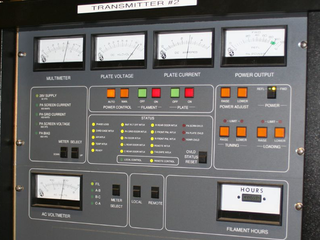
In electronics and telecommunications, a radio transmitter or just transmitter is an electronic device which produces radio waves with an antenna with the purpose of signal transmission up to a radio receiver. The transmitter itself generates a radio frequency alternating current, which is applied to the antenna. When excited by this alternating current, the antenna radiates radio waves.

<span class="mw-page-title-main">Radio wave</span> Type of electromagnetic radiation

Radio waves are a type of electromagnetic radiation with the lowest frequencies and the longest wavelengths in the electromagnetic spectrum, typically with frequencies below 300 gigahertz (GHz) and wavelengths greater than 1 millimeter, about the diameter of a grain of rice. Like all electromagnetic waves, radio waves in a vacuum travel at the speed of light, and in the Earth's atmosphere at a slightly slower speed. Radio waves are generated by charged particles undergoing acceleration, such as time-varying electric currents. Naturally occurring radio waves are emitted by lightning and astronomical objects, and are part of the blackbody radiation emitted by all warm objects.

<span class="mw-page-title-main">Antenna (radio)</span> Electrical device

In radio engineering, an antenna or aerial is the interface between radio waves propagating through space and electric currents moving in metal conductors, used with a transmitter or receiver. In transmission, a radio transmitter supplies an electric current to the antenna's terminals, and the antenna radiates the energy from the current as electromagnetic waves. In reception, an antenna intercepts some of the power of a radio wave in order to produce an electric current at its terminals, that is applied to a receiver to be amplified. Antennas are essential components of all radio equipment.

<span class="mw-page-title-main">Parabolic antenna</span> Type of antenna

A parabolic antenna is an antenna that uses a parabolic reflector, a curved surface with the cross-sectional shape of a parabola, to direct the radio waves. The most common form is shaped like a dish and is popularly called a dish antenna or parabolic dish. The main advantage of a parabolic antenna is that it has high directivity. It functions similarly to a searchlight or flashlight reflector to direct radio waves in a narrow beam, or receive radio waves from one particular direction only. Parabolic antennas have some of the highest gains, meaning that they can produce the narrowest beamwidths, of any antenna type. In order to achieve narrow beamwidths, the parabolic reflector must be much larger than the wavelength of the radio waves used, so parabolic antennas are used in the high frequency part of the radio spectrum, at UHF and microwave (SHF) frequencies, at which the wavelengths are small enough that conveniently sized reflectors can be used.

<span class="mw-page-title-main">Low-noise block downconverter</span> Receiving device on satellite dishes

A low-noise block downconverter (LNB) is the receiving device mounted on satellite dishes used for satellite TV reception, which collects the radio waves from the dish and converts them to a signal which is sent through a cable to the receiver inside the building. Also called a low-noise block, low-noise converter (LNC), or even low-noise downconverter (LND), the device is sometimes inaccurately called a low-noise amplifier (LNA).

This is an index of articles relating to electronics and electricity or natural electricity and things that run on electricity and things that use or conduct electricity.

<span class="mw-page-title-main">Slot antenna</span>

A slot antenna consists of a metal surface, usually a flat plate, with one or more holes or slots cut out. When the plate is driven as an antenna by an applied radio frequency current, the slot radiates electromagnetic waves in a way similar to a dipole antenna. The shape and size of the slot, as well as the driving frequency, determine the radiation pattern. Slot antennas are usually used at UHF and microwave frequencies at which wavelengths are small enough that the plate and slot are conveniently small. At these frequencies, the radio waves are often conducted by a waveguide, and the antenna consists of slots in the waveguide; this is called a slotted waveguide antenna. Multiple slots act as a directive array antenna and can emit a narrow fan-shaped beam of microwaves. They are used in standard laboratory microwave sources used for research, UHF television transmitting antennas, antennas on missiles and aircraft, sector antennas for cellular base stations, and particularly marine radar antennas. A slot antenna's main advantages are its size, design simplicity, and convenient adaptation to mass production using either waveguide or PC board technology.

<span class="mw-page-title-main">Orthomode transducer</span> Component for guiding radio waves

An orthomode transducer (OMT) is a waveguide component that is commonly referred to as a polarisation duplexer. Orthomode is a contraction of orthogonal mode. Orthomode transducers serve either to combine or to separate two orthogonally polarized microwave signal paths. One of the paths forms the uplink, which is transmitted over the same waveguide as the received signal path, or downlink path. Such a device may be part of a very small aperture terminal (VSAT) antenna feed or a terrestrial microwave radio feed; for example, OMTs are often used with a feed horn to isolate orthogonal polarizations of a signal and to transfer transmit and receive signals to different ports.

<span class="mw-page-title-main">Antenna diversity</span> Redundancy method to improve communications reliability

Antenna diversity, also known as space diversity or spatial diversity, is any one of several wireless diversity schemes that uses two or more antennas to improve the quality and reliability of a wireless link. Often, especially in urban and indoor environments, there is no clear line-of-sight (LOS) between transmitter and receiver. Instead the signal is reflected along multiple paths before finally being received. Each of these bounces can introduce phase shifts, time delays, attenuations, and distortions that can destructively interfere with one another at the aperture of the receiving antenna.

<span class="mw-page-title-main">Waveguide (radio frequency)</span> Hollow metal pipe used to carry radio waves

In radio-frequency engineering and communications engineering, waveguide is a hollow metal pipe used to carry radio waves. This type of waveguide is used as a transmission line mostly at microwave frequencies, for such purposes as connecting microwave transmitters and receivers to their antennas, in equipment such as microwave ovens, radar sets, satellite communications, and microwave radio links.

A radio transmitter or receiver is connected to an antenna which emits or receives the radio waves. The antenna feed system or antenna feed is the cable or conductor, and other associated equipment, which connects the transmitter or receiver with the antenna and makes the two devices compatible. In a radio transmitter, the transmitter generates an alternating current of radio frequency, and the feed system feeds the current to the antenna, which converts the power in the current to radio waves. In a radio receiver, the incoming radio waves excite tiny alternating currents in the antenna, and the feed system delivers this current to the receiver, which processes the signal.

<span class="mw-page-title-main">AN/SPG-55</span>

The AN/SPG-55 was an American tracking / illumination radar for Terrier and RIM-67 Standard missiles (SM-1ER/SM-2ER). It was used for target tracking and surface-to-air missile guidance as part of the Mk 76 missile fire control system. It was controlled by a UNIVAC 1218 computer.

<span class="mw-page-title-main">Vivaldi antenna</span> Type of broadband antenna

A Vivaldi antenna or Vivaldi aerial or tapered slot antenna is a co-planar broadband-antenna, which can be made from a solid piece of sheet metal, a printed circuit board, or from a dielectric plate metalized on one or both sides.

A radio science subsystem (RSS) is a subsystem placed on board a spacecraft for radio science purposes.

<span class="mw-page-title-main">Waveguide filter</span> Electronic filter that is constructed with waveguide technology

A waveguide filter is an electronic filter constructed with waveguide technology. Waveguides are hollow metal conduits inside which an electromagnetic wave may be transmitted. Filters are devices used to allow signals at some frequencies to pass, while others are rejected. Filters are a basic component of electronic engineering designs and have numerous applications. These include selection of signals and limitation of noise. Waveguide filters are most useful in the microwave band of frequencies, where they are a convenient size and have low loss. Examples of microwave filter use are found in satellite communications, telephone networks, and television broadcasting.

<span class="mw-page-title-main">XPIC</span>

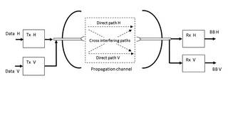
XPIC, or cross-polarization interference cancelling technology, is an algorithm to suppress mutual interference between two received streams in a Polarization-division multiplexing communication system.

In radio systems, many different antenna types are used whose properties are especially crafted for particular applications. Most often, the greatest effect is due to the size (wavelength) of the radio waves the antenna is to intercept or produce; one competing second effect is differences in optimization for receiving and for transmitting; another competing influence is the number and bandwidth of the frequenc(y/ies) that any single antenna must intercept or emit.

<span class="mw-page-title-main">Wireless Set Number 10</span> Worlds first microwave relay telephone system

The British Army's Wireless Set, Number 10, was the world's first microwave relay telephone system. It transmitted eight full-duplex (two-way) telephone channels between two stations limited only by the line-of-sight, often on the order of 25 to 50 miles. The stations were mounted in highly mobile trailers and were set up simply by aiming the two parabolic antennas on the roof at the next station.

References

  1. She, Alan; Capasso, Federico (17 May 2016). "Parallel Polarization State Generation". Scientific Reports. 6. Nature: 26019. arXiv: 1602.04463 . Bibcode:2016NatSR...626019S. doi:10.1038/srep26019. PMC   4869035 . PMID   27184813.
  2. The Road to 100G Networking, Ciena, 2008