
Bandwidth is the difference between the upper and lower frequencies in a continuous band of frequencies. It is typically measured in unit of hertz.

Frequency modulation (FM) is the encoding of information in a carrier wave by varying the instantaneous frequency of the wave. The technology is used in telecommunications, radio broadcasting, signal processing, and computing.
In electronics and telecommunications, modulation is the process of varying one or more properties of a periodic waveform, called the carrier signal, with a separate signal called the modulation signal that typically contains information to be transmitted. For example, the modulation signal might be an audio signal representing sound from a microphone, a video signal representing moving images from a video camera, or a digital signal representing a sequence of binary digits, a bitstream from a computer.

In telecommunications, orthogonal frequency-division multiplexing (OFDM) is a type of digital transmission used in digital modulation for encoding digital (binary) data on multiple carrier frequencies. OFDM has developed into a popular scheme for wideband digital communication, used in applications such as digital television and audio broadcasting, DSL internet access, wireless networks, power line networks, and 4G/5G mobile communications.
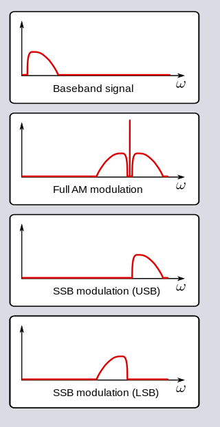
In radio communications, single-sideband modulation (SSB) or single-sideband suppressed-carrier modulation (SSB-SC) is a type of modulation used to transmit information, such as an audio signal, by radio waves. A refinement of amplitude modulation, it uses transmitter power and bandwidth more efficiently. Amplitude modulation produces an output signal the bandwidth of which is twice the maximum frequency of the original baseband signal. Single-sideband modulation avoids this bandwidth increase, and the power wasted on a carrier, at the cost of increased device complexity and more difficult tuning at the receiver.

In telecommunications and signal processing, baseband is the range of frequencies occupied by a signal that has not been modulated to higher frequencies. Baseband signals typically originate from transducers, converting some other variable into an electrical signal. For example, the electronic output of a microphone is a baseband signal that is analogous to the applied voice audio. In conventional analog radio broadcasting, the baseband audio signal is used to modulate an RF carrier signal of a much higher frequency.

Frequency-shift keying (FSK) is a frequency modulation scheme in which digital information is encoded on a carrier signal by periodically shifting the frequency of the carrier between several discrete frequencies. The technology is used for communication systems such as telemetry, weather balloon radiosondes, caller ID, garage door openers, and low frequency radio transmission in the VLF and ELF bands. The simplest FSK is binary FSK, in which the carrier is shifted between two discrete frequencies to transmit binary information.
In signal processing, group delay and phase delay are two related ways of describing how a signal's frequency components are delayed in time when passing through a linear time-invariant (LTI) system. Phase delay describes the time shift of a sinusoidal component. Group delay describes the time shift of the envelope of a wave packet, a "pack" or "group" of oscillations centered around one frequency that travel together, formed for instance by multiplying a sine wave by an envelope.

In signal processing, the Nyquist rate, named after Harry Nyquist, is a value equal to twice the highest frequency (bandwidth) of a given function or signal. When the function is digitized at a higher sample rate, the resulting discrete-time sequence is said to be free of the distortion known as aliasing. Conversely, for a given sample-rate the corresponding Nyquist frequency in Hz is one-half the sample-rate. Note that the Nyquist rate is a property of a continuous-time signal, whereas Nyquist frequency is a property of a discrete-time system.
Data communication, including data transmission and data reception, is the transfer of data, transmitted and received over a point-to-point or point-to-multipoint communication channel. Examples of such channels are copper wires, optical fibers, wireless communication using radio spectrum, storage media and computer buses. The data are represented as an electromagnetic signal, such as an electrical voltage, radiowave, microwave, or infrared signal.

In telecommunications, frequency-division multiplexing (FDM) is a technique by which the total bandwidth available in a communication medium is divided into a series of non-overlapping frequency bands, each of which is used to carry a separate signal. This allows a single transmission medium such as a microwave radio link, cable or optical fiber to be shared by multiple independent signals. Another use is to carry separate serial bits or segments of a higher rate signal in parallel.

In telecommunications, a carrier wave, carrier signal, or just carrier, is a waveform that is modulated (modified) with an information-bearing signal for the purpose of conveying information.

A band-pass filter or bandpass filter (BPF) is a device that passes frequencies within a certain range and rejects (attenuates) frequencies outside that range. It's the opposite of a band-stop filter.
This is an index of articles relating to electronics and electricity or natural electricity and things that run on electricity and things that use or conduct electricity.

In radio communications, a radio receiver, also known as a receiver, a wireless, or simply a radio, is an electronic device that receives radio waves and converts the information carried by them to a usable form. It is used with an antenna. The antenna intercepts radio waves and converts them to tiny alternating currents which are applied to the receiver, and the receiver extracts the desired information. The receiver uses electronic filters to separate the desired radio frequency signal from all the other signals picked up by the antenna, an electronic amplifier to increase the power of the signal for further processing, and finally recovers the desired information through demodulation.
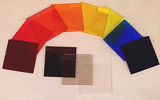
An optical filter is a device that selectively transmits light of different wavelengths, usually implemented as a glass plane or plastic device in the optical path, which are either dyed in the bulk or have interference coatings. The optical properties of filters are completely described by their frequency response, which specifies how the magnitude and phase of each frequency component of an incoming signal is modified by the filter.

Continuous-wave radar is a type of radar system where a known stable frequency continuous wave radio energy is transmitted and then received from any reflecting objects. Individual objects can be detected using the Doppler effect, which causes the received signal to have a different frequency from the transmitted signal, allowing it to be detected by filtering out the transmitted frequency.
Spectral efficiency, spectrum efficiency or bandwidth efficiency refers to the information rate that can be transmitted over a given bandwidth in a specific communication system. It is a measure of how efficiently a limited frequency spectrum is utilized by the physical layer protocol, and sometimes by the medium access control.
In a digitally modulated signal or a line code, symbol rate, modulation rate or baud rate is the number of symbol changes, waveform changes, or signaling events across the transmission medium per unit of time. The symbol rate is measured in baud (Bd) or symbols per second. In the case of a line code, the symbol rate is the pulse rate in pulses per second. Each symbol can represent or convey one or several bits of data. The symbol rate is related to the gross bit rate, expressed in bits per second.
In electronics and telecommunications, pulse shaping is the process of changing a transmitted pulses' waveform to optimize the signal for its intended purpose or the communication channel. This is often done by limiting the bandwidth of the transmission and filtering the pulses to control intersymbol interference. Pulse shaping is particularly important in RF communication for fitting the signal within a certain frequency band and is typically applied after line coding and modulation.

