Baseband

Last updated
Spectrum of a baseband signal, energy E per unit frequency as a function of frequency f. The total energy is the area under the curve. Bandlimited2.svg
Spectrum of a baseband signal, energy E per unit frequency as a function of frequency f. The total energy is the area under the curve.

In telecommunications and signal processing, baseband is the range of frequencies occupied by a signal that has not been modulated to higher frequencies. [1] Baseband signals typically originate from transducers, converting some other variable into an electrical signal. For example, the electronic output of a microphone is a baseband signal that is analogous to the applied voice audio. In conventional analog radio broadcasting, the baseband audio signal is used to modulate an RF carrier signal of a much higher frequency.

Contents

A baseband signal may have frequency components going all the way down to the DC bias, or at least it will have a high ratio bandwidth. A modulated baseband signal is called a passband signal. This occupies a higher range of frequencies and has a lower ratio and fractional bandwidth.

Various uses

Baseband signal

A baseband signal or lowpass signal is a signal that can include frequencies that are very near zero, by comparison with its highest frequency (for example, a sound waveform can be considered as a baseband signal, whereas a radio signal or any other modulated signal is not). [2]

A baseband bandwidth is equal to the highest frequency of a signal or system, or an upper bound on such frequencies, [3] for example the upper cut-off frequency of a low-pass filter. By contrast, passband bandwidth is the difference between a highest frequency and a nonzero lowest frequency.

Baseband channel

A baseband channel or lowpass channel (or system, or network) is a communication channel that can transfer frequencies that are very near zero. [4] Examples are serial cables and local area networks (LANs), as opposed to passband channels such as radio frequency channels and passband filtered wires of the analog telephone network. Frequency division multiplexing (FDM) allows an analog telephone wire to carry a baseband telephone call, concurrently as one or several carrier-modulated telephone calls.

Digital baseband transmission

Digital baseband transmission, also known as line coding, [5] aims at transferring a digital bit stream over baseband channel, typically an unfiltered wire, contrary to passband transmission, also known as carrier-modulated transmission. [6] Passband transmission makes communication possible over a bandpass filtered channel, such as the telephone network local-loop or a band-limited wireless channel. [7]

Baseband transmission in Ethernet

The word "BASE" in Ethernet physical layer standards, for example 10BASE5, 100BASE-TX and 1000BASE-SX, implies baseband digital transmission (i.e. that a line code and an unfiltered wire are used). [8] [9]

Baseband processor

A baseband processor also known as BP or BBP is used to process the down-converted digital signal to retrieve essential data for a wireless digital system. The baseband processing block in GNSS receivers is responsible for providing observable data: that is, code pseudo-ranges and carrier phase measurements, as well as navigation data. [7]

Equivalent baseband signal

On the left is a part of the transmitter, which will take in a stream of IQ data, and use this to amplitude modulate a Local Oscillator's signal, both the standard sine wave from the LO, and also a version which phase shifted by 90deg (in-phase and quadrature) - these modulated signals are combined, to form the Intermediate frequency IF representation. In a typical transmitter, the IF would get up-converted, filtered, amplified, then transmitted from an antenna.
On the right we see an aspect of the receiver. After some low-noise amplification, filtering and down-conversion to an Intermediate Frequency, the signal is split into two, and one aspect is mixed with the in-phase sine from the LO, and the other from the quadrature version, giving a complex (or 2-dimensional) representation of the signal. This IQ data could then be supplied to a digital signal processor to extract symbols or data. IQ Mod Demod block diagram.svg
On the left is a part of the transmitter, which will take in a stream of IQ data, and use this to amplitude modulate a Local Oscillator's signal, both the standard sine wave from the LO, and also a version which phase shifted by 90° (in-phase and quadrature) - these modulated signals are combined, to form the Intermediate frequency IF representation. In a typical transmitter, the IF would get up-converted, filtered, amplified, then transmitted from an antenna.
On the right we see an aspect of the receiver. After some low-noise amplification, filtering and down-conversion to an Intermediate Frequency, the signal is split into two, and one aspect is mixed with the in-phase sine from the LO, and the other from the quadrature version, giving a complex (or 2-dimensional) representation of the signal. This IQ data could then be supplied to a digital signal processor to extract symbols or data.

An equivalent baseband signal or equivalent lowpass signal is a complex valued representation of the modulated physical signal (the so-called passband signal or RF signal). It is a concept within analog and digital modulation methods for (passband) signals with constant or varying carrier frequency (for example ASK, PSK QAM, and FSK). The equivalent baseband signal is where is the inphase signal, the quadrature phase signal, and the imaginary unit. This signal is sometimes called IQ data . In a digital modulation method, the and signals of each modulation symbol are evident from the constellation diagram. The frequency spectrum of this signal includes negative as well as positive frequencies. The physical passband signal corresponds to

where is the carrier angular frequency in rad/s. [10]

Modulation

A signal at baseband is often used to modulate a higher frequency carrier signal in order that it may be transmitted via radio. Modulation results in shifting the signal up to much higher frequencies (radio frequencies, or RF) than it originally spanned. A key consequence of the usual double-sideband amplitude modulation (AM) is that the range of frequencies the signal spans (its spectral bandwidth) is doubled. Thus, the RF bandwidth of a signal (measured from the lowest frequency as opposed to 0 Hz) is twice its baseband bandwidth. Steps may be taken to reduce this effect, such as single-sideband modulation. Conversely, some transmission schemes such as frequency modulation use even more bandwidth.

The figure below shows AM modulation:

Comparison of the equivalent baseband version of a signal and its AM-modulated (double-sideband) RF version, showing the typical doubling of the occupied bandwidth. Baseband to RF.svg
Comparison of the equivalent baseband version of a signal and its AM-modulated (double-sideband) RF version, showing the typical doubling of the occupied bandwidth.

See also

Related Research Articles

<span class="mw-page-title-main">Amplitude modulation</span> Radio modulation via wave amplitude

Amplitude modulation (AM) is a modulation technique used in electronic communication, most commonly for transmitting messages with a radio wave. In amplitude modulation, the amplitude of the wave is varied in proportion to that of the message signal, such as an audio signal. This technique contrasts with angle modulation, in which either the frequency of the carrier wave is varied, as in frequency modulation, or its phase, as in phase modulation.

<span class="mw-page-title-main">Bandwidth (signal processing)</span> Range of usable frequencies

Bandwidth is the difference between the upper and lower frequencies in a continuous band of frequencies. It is typically measured in unit of hertz.

<span class="mw-page-title-main">Frequency modulation</span> Encoding of information in a carrier wave by varying the instantaneous frequency of the wave

Frequency modulation (FM) is the encoding of information in a carrier wave by varying the instantaneous frequency of the wave. The technology is used in telecommunications, radio broadcasting, signal processing, and computing.

In electronics and telecommunications, modulation is the process of varying one or more properties of a periodic waveform, called the carrier signal, with a separate signal called the modulation signal that typically contains information to be transmitted. For example, the modulation signal might be an audio signal representing sound from a microphone, a video signal representing moving images from a video camera, or a digital signal representing a sequence of binary digits, a bitstream from a computer.

<span class="mw-page-title-main">Orthogonal frequency-division multiplexing</span> Method of encoding digital data on multiple carrier frequencies

In telecommunications, orthogonal frequency-division multiplexing (OFDM) is a type of digital transmission used in digital modulation for encoding digital (binary) data on multiple carrier frequencies. OFDM has developed into a popular scheme for wideband digital communication, used in applications such as digital television and audio broadcasting, DSL internet access, wireless networks, power line networks, and 4G/5G mobile communications.

Phase modulation (PM) is a modulation pattern for conditioning communication signals for transmission. It encodes a message signal as variations in the instantaneous phase of a carrier wave. Phase modulation is one of the two principal forms of angle modulation, together with frequency modulation.

Quadrature amplitude modulation (QAM) is the name of a family of digital modulation methods and a related family of analog modulation methods widely used in modern telecommunications to transmit information. It conveys two analog message signals, or two digital bit streams, by changing (modulating) the amplitudes of two carrier waves, using the amplitude-shift keying (ASK) digital modulation scheme or amplitude modulation (AM) analog modulation scheme. The two carrier waves are of the same frequency and are out of phase with each other by 90°, a condition known as orthogonality or quadrature. The transmitted signal is created by adding the two carrier waves together. At the receiver, the two waves can be coherently separated (demodulated) because of their orthogonality. Another key property is that the modulations are low-frequency/low-bandwidth waveforms compared to the carrier frequency, which is known as the narrowband assumption.

<span class="mw-page-title-main">Single-sideband modulation</span> Type of modulation

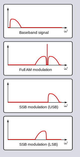
In radio communications, single-sideband modulation (SSB) or single-sideband suppressed-carrier modulation (SSB-SC) is a type of modulation used to transmit information, such as an audio signal, by radio waves. A refinement of amplitude modulation, it uses transmitter power and bandwidth more efficiently. Amplitude modulation produces an output signal the bandwidth of which is twice the maximum frequency of the original baseband signal. Single-sideband modulation avoids this bandwidth increase, and the power wasted on a carrier, at the cost of increased device complexity and more difficult tuning at the receiver.

<span class="mw-page-title-main">Nyquist–Shannon sampling theorem</span> Sufficiency theorem for reconstructing signals from samples

The Nyquist–Shannon sampling theorem is an essential principle for digital signal processing linking the frequency range of a signal and the sample rate required to avoid a type of distortion called aliasing. The theorem states that the sample rate must be at least twice the bandwidth of the signal to avoid aliasing. In practice, it is used to select band-limiting filters to keep aliasing below an acceptable amount when an analog signal is sampled or when sample rates are changed within a digital signal processing function.

In signal processing, group delay and phase delay are two related ways of describing how a signal's frequency components are delayed in time when passing through a linear time-invariant (LTI) system. Phase delay describes the time shift of a sinusoidal component. Group delay describes the time shift of the envelope of a wave packet, a "pack" or "group" of oscillations centered around one frequency that travel together, formed for instance by multiplying a sine wave by an envelope.

A passband is the range of frequencies or wavelengths that can pass through a filter. For example, a radio receiver contains a bandpass filter to select the frequency of the desired radio signal out of all the radio waves picked up by its antenna. The passband of a receiver is the range of frequencies it can receive when it is tuned into the desired frequency (channel).

<span class="mw-page-title-main">Sideband</span> Radio communications concept

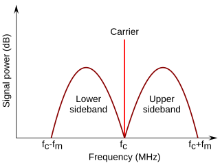
In radio communications, a sideband is a band of frequencies higher than or lower than the carrier frequency, that are the result of the modulation process. The sidebands carry the information transmitted by the radio signal. The sidebands comprise all the spectral components of the modulated signal except the carrier. The signal components above the carrier frequency constitute the upper sideband (USB), and those below the carrier frequency constitute the lower sideband (LSB). All forms of modulation produce sidebands.

Data communication or digital communications, including data transmission and data reception, is the transfer and reception of data in the form of a digital bitstream or a digitized analog signal transmitted over a point-to-point or point-to-multipoint communication channel. Examples of such channels are copper wires, optical fibers, wireless communication using radio spectrum, storage media and computer buses. The data are represented as an electromagnetic signal, such as an electrical voltage, radiowave, microwave, or infrared signal.

<span class="mw-page-title-main">Frequency-division multiplexing</span> Signal processing technique in telecommunications

In telecommunications, frequency-division multiplexing (FDM) is a technique by which the total bandwidth available in a communication medium is divided into a series of non-overlapping frequency bands, each of which is used to carry a separate signal. This allows a single transmission medium such as a microwave radio link, cable or optical fiber to be shared by multiple independent signals. Another use is to carry separate serial bits or segments of a higher rate signal in parallel.

Angle modulation is a class of carrier modulation that is used in telecommunications transmission systems. The class comprises frequency modulation (FM) and phase modulation (PM), and is based on altering the frequency or the phase, respectively, of a carrier signal to encode the message signal. This contrasts with varying the amplitude of the carrier, practiced in amplitude modulation (AM) transmission, the earliest of the major modulation methods used widely in early radio broadcasting.

This is an index of articles relating to electronics and electricity or natural electricity and things that run on electricity and things that use or conduct electricity.

Spectral efficiency, spectrum efficiency or bandwidth efficiency refers to the information rate that can be transmitted over a given bandwidth in a specific communication system. It is a measure of how efficiently a limited frequency spectrum is utilized by the physical layer protocol, and sometimes by the medium access control.

<span class="mw-page-title-main">Delta-sigma modulation</span> Method for converting signals between digital and analog

Delta-sigma modulation is an oversampling method for encoding signals into low bit depth digital signals at a very high sample-frequency as part of the process of delta-sigma analog-to-digital converters (ADCs) and digital-to-analog converters (DACs). Delta-sigma modulation achieves high quality by utilizing a negative feedback loop during quantization to the lower bit depth that continuously corrects quantization errors and moves quantization noise to higher frequencies well above the original signal's bandwidth. Subsequent low-pass filtering for demodulation easily removes this high frequency noise and time averages to achieve high accuracy in amplitude which can be ultimately encoded as pulse-code modulation (PCM).

In a digitally modulated signal or a line code, symbol rate, modulation rate or baud rate is the number of symbol changes, waveform changes, or signaling events across the transmission medium per unit of time. The symbol rate is measured in baud (Bd) or symbols per second. In the case of a line code, the symbol rate is the pulse rate in pulses per second. Each symbol can represent or convey one or several bits of data. The symbol rate is related to the gross bit rate, expressed in bits per second.

<span class="mw-page-title-main">Carrier recovery</span>

A carrier recovery system is a circuit used to estimate and compensate for frequency and phase differences between a received signal's carrier wave and the receiver's local oscillator for the purpose of coherent demodulation.

References

  1. Jeff Rutenbeck, Tech Terms: What Every Telecommunications and Digital Media Professional Should Know, p. 24, CRC Press, 2012 ISBN   1136034501
  2. Steven Alan Tretter (1995). Communication System Design Using Dsp Algorithms: With Laboratory Experiments for the TMS320C30. Springer. ISBN   0-306-45032-1.
  3. Mischa Schwartz (1970). Information, Transmission, Modulation and Noise: A Unified Approach to Communication Systems. McGraw-Hill. ISBN   9780070557611.
  4. Chris C. Bissell and David A. Chapman (1992). Digital Signal Transmission. Cambridge University Press. ISBN   0-521-42557-3.
  5. Mikael Gustavsson and J. Jacob Wikner (2000). CMOS Data Converters for Communications. Springer. ISBN   0-7923-7780-X.
  6. Jan W. M. Bergmans (1996). Digital Baseband Transmission and Recording. Springer. ISBN   0-7923-9775-4.
  7. 1 2 "Baseband Processing - Navipedia". gssc.esa.int. Retrieved 2022-07-04.
  8. IEEE 802.3 1.2.3 Physical layer and media notation
  9. "IEEE Get Program". standards.ieee.org. IEEE. Retrieved 29 March 2017.
  10. Proakis, John G. Digital Communications, 4th edition. McGraw-Hill, 2001. p150