Related Research Articles
Ethernet is a family of wired computer networking technologies commonly used in local area networks (LAN), metropolitan area networks (MAN) and wide area networks (WAN). It was commercially introduced in 1980 and first standardized in 1983 as IEEE 802.3. Ethernet has since been refined to support higher bit rates, a greater number of nodes, and longer link distances, but retains much backward compatibility. Over time, Ethernet has largely replaced competing wired LAN technologies such as Token Ring, FDDI and ARCNET.
100BaseVG is a 100 Mbit/s Ethernet standard specified to run over four pairs of Category 3 cable. It is also called 100VG-AnyLAN because it was defined to carry both Ethernet and Token Ring frame types.

10BASE2 is a variant of Ethernet that uses thin coaxial cable terminated with BNC connectors to build a local area network.
10BASE5 was the first commercially available variant of Ethernet. The technology was standardized in 1982 as IEEE 802.3. 10BASE5 uses a thick and stiff coaxial cable up to 500 meters (1,600 ft) in length. Up to 100 stations can be connected to the cable using vampire taps and share a single collision domain with 10 Mbit/s of bandwidth shared among them. The system is difficult to install and maintain.
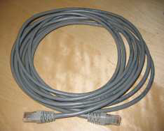
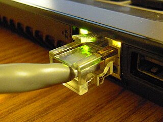
Ethernet over twisted-pair technologies use twisted-pair cables for the physical layer of an Ethernet computer network. They are a subset of all Ethernet physical layers.
Carrier-sense multiple access with collision detection (CSMA/CD) is a medium access control (MAC) method used most notably in early Ethernet technology for local area networking. It uses carrier-sensing to defer transmissions until no other stations are transmitting. This is used in combination with collision detection in which a transmitting station detects collisions by sensing transmissions from other stations while it is transmitting a frame. When this collision condition is detected, the station stops transmitting that frame, transmits a jam signal, and then waits for a random time interval before trying to resend the frame.

In computer networking, Fast Ethernet physical layers carry traffic at the nominal rate of 100 Mbit/s. The prior Ethernet speed was 10 Mbit/s. Of the Fast Ethernet physical layers, 100BASE-TX is by far the most common.
In the seven-layer OSI model of computer networking, the physical layer or layer 1 is the first and lowest layer: the layer most closely associated with the physical connection between devices. The physical layer provides an electrical, mechanical, and procedural interface to the transmission medium. The shapes and properties of the electrical connectors, the frequencies to transmit on, the line code to use and similar low-level parameters, are specified by the physical layer.
In the IEEE 802 reference model of computer networking, the logical link control (LLC) data communication protocol layer is the upper sublayer of the data link layer of the seven-layer OSI model. The LLC sublayer acts as an interface between the medium access control (MAC) sublayer and the network layer.
The data link layer, or layer 2, is the second layer of the seven-layer OSI model of computer networking. This layer is the protocol layer that transfers data between nodes on a network segment across the physical layer. The data link layer provides the functional and procedural means to transfer data between network entities and may also provide the means to detect and possibly correct errors that can occur in the physical layer.
A collision domain is a network segment connected by a shared medium or through repeaters where simultaneous data transmissions collide with one another. The collision domain applies particularly in wireless networks, but also affected early versions of Ethernet. A network collision occurs when more than one device attempts to send a packet on a network segment at the same time. Members of a collision domain may be involved in collisions with one another. Devices outside the collision domain do not have collisions with those inside.
StarLAN was the first IEEE 802.3 standard for Ethernet over twisted pair wiring. It was standardized by the IEEE Standards Association as 802.3e in 1986, as the 1BASE5 version of Ethernet. The StarLAN Task Force was chaired by Bob Galin.

In IEEE 802 LAN/MAN standards, the medium access control (MAC), also called media access control, is the layer that controls the hardware responsible for interaction with the wired or wireless transmission medium. The MAC sublayer and the logical link control (LLC) sublayer together make up the data link layer. The LLC provides flow control and multiplexing for the logical link, while the MAC provides flow control and multiplexing for the transmission medium.
A network segment is a portion of a computer network. The nature and extent of a segment depends on the nature of the network and the device or devices used to interconnect end stations.
The media-independent interface (MII) was originally defined as a standard interface to connect a Fast Ethernet medium access control (MAC) block to a PHY chip. The MII is standardized by IEEE 802.3u and connects different types of PHYs to MACs. Being media independent means that different types of PHY devices for connecting to different media can be used without redesigning or replacing the MAC hardware. Thus any MAC may be used with any PHY, independent of the network signal transmission medium.
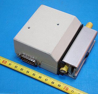
A Medium Attachment Unit (MAU) is a transceiver which converts signals on an Ethernet cable to and from Attachment Unit Interface (AUI) signals.
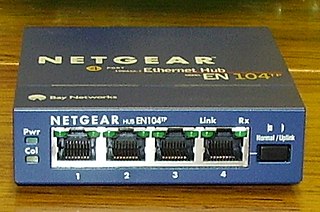
An Ethernet hub, active hub, network hub, repeater hub, multiport repeater, or simply hub is a network hardware device for connecting multiple Ethernet devices together and making them act as a single network segment. It has multiple input/output (I/O) ports, in which a signal introduced at the input of any port appears at the output of every port except the original incoming. A hub works at the physical layer. A repeater hub also participates in collision detection, forwarding a jam signal to all ports if it detects a collision. In addition to standard 8P8C ("RJ45") ports, some hubs may also come with a BNC or an Attachment Unit Interface (AUI) connector to allow connection to legacy 10BASE2 or 10BASE5 network segments.
Autonegotiation is a signaling mechanism and procedure used by Ethernet over twisted pair by which two connected devices choose common transmission parameters, such as speed, duplex mode, and flow control. In this process, the connected devices first share their capabilities regarding these parameters and then choose the highest performance transmission mode they both support.

The physical-layer specifications of the Ethernet family of computer network standards are published by the Institute of Electrical and Electronics Engineers (IEEE), which defines the electrical or optical properties and the transfer speed of the physical connection between a device and the network or between network devices. It is complemented by the MAC layer and the logical link layer. An implementation of a specific physical layer is commonly referred to as PHY.
Classic Ethernet is a family of 10 Mbit/s Ethernet standards, which is the first generation of Ethernet standards. In 10BASE-X, the 10 represents its maximum throughput of 10 Mbit/s, BASE indicates its use of baseband transmission, and X indicates the type of medium used. Classic Ethernet includes coax, twisted pair and optical variants. The first Ethernet standard was published in 1983 and classic Ethernet operating at 10 Mbit/s was the dominant form of Ethernet until the first standard for Fast Ethernet was approved in 1995.
References
- ↑ "IEEE 802.3-2012 13. System considerations for multisegment 10 Mb/s baseband networks". IEEE 802.3. 8 December 2012. Retrieved 15 November 2015.
- ↑ Helmig, Johannes (28 October 1997). "Large Networks: 5-4-3 Rule". WindowsNetworking.com. Archived from the original on 18 August 2010.
- ↑ Mitchell, Bradley. "The 5-4-3-2-1 Rule". About.com. Archived from the original on 6 December 2010.
- ↑ IEEE 802.3 13.4 Transmission System Model 2
- ↑ IEEE 802.3 13. System considerations for multisegment 10 Mb/s baseband networks
- ↑ "1.4.318", 802.3-2008 Part 3: Carrier sense multiple access with Collision Detection (CSMA/CD) Access Method and Physical Layer Specifications, IEEE, 26 December 2008,
segment: The medium connection, including connectors, between Medium Dependent Interfaces (MDIs) in a CSMA/CD local area network.
- ↑ An Educator's Guide to School Networks, Florida Center for Instructional Technology, retrieved 4 September 2010
- ↑ IEEE 802.3-2003 section 7.2.3.2 "Preamble"
Ethernet family of local area network technologies | |
|---|---|
| Speeds | |
| General | |
| Organizations | |
| Media | |
| Historic | |
| Applications | |
| Transceivers | |
| Interfaces | |