Automatic gain control

Last updated
Schematic of an AGC used in the analog telephone network; the feedback from output level to gain is effected via a Vactrol resistive opto-isolator. Vactrol AGC (Yushin).PNG
Schematic of an AGC used in the analog telephone network; the feedback from output level to gain is effected via a Vactrol resistive opto-isolator.

Automatic gain control (AGC) is a closed-loop feedback regulating circuit in an amplifier or chain of amplifiers, the purpose of which is to maintain a suitable signal amplitude at its output, despite variation of the signal amplitude at the input. The average or peak output signal level is used to dynamically adjust the gain of the amplifiers, enabling the circuit to work satisfactorily with a greater range of input signal levels. It is used in most radio receivers to equalize the average volume (loudness) of different radio stations due to differences in received signal strength, as well as variations in a single station's radio signal due to fading. Without AGC the sound emitted from an AM radio receiver would vary to an extreme extent from a weak to a strong signal; the AGC effectively reduces the volume if the signal is strong and raises it when it is weaker. In a typical receiver the AGC feedback control signal is usually taken from the detector stage and applied to control the gain of the IF or RF amplifier stages.

Contents

How it works

The signal to be gain controlled (the detector output in a radio) goes to a diode & capacitor, which produce a peak-following DC voltage. This is fed to the RF gain blocks to alter their bias, thus altering their gain. Traditionally all the gain-controlled stages came before the signal detection, but it is also possible to improve gain control by adding a gain-controlled stage after signal detection.

Example use cases

AM radio receivers

In 1925, Harold Alden Wheeler invented automatic volume control (AVC) and obtained a patent. Karl Küpfmüller published an analysis of AGC systems in 1928. [1] By the early 1930s most new commercial broadcast receivers included automatic volume control. [2]

AGC is a departure from linearity in AM radio receivers. [3] Without AGC, an AM radio would have a linear relationship between the signal amplitude and the sound waveform – the sound amplitude, which correlates with loudness, is proportional to the radio signal amplitude, because the information content of the signal is carried by the changes of amplitude of the carrier wave. If the circuit were not fairly linear, the modulated signal could not be recovered with reasonable fidelity. However, the strength of the signal received will vary widely, depending on the power and distance of the transmitter, and signal path attenuation. The AGC circuit keeps the receiver's output level from fluctuating too much by detecting the overall strength of the signal and automatically adjusting the gain of the receiver to maintain the output level within an acceptable range. For a very weak signal, the AGC operates the receiver at maximum gain; as the signal increases, the AGC reduces the gain.

It is usually disadvantageous to reduce the gain of the RF front end of the receiver on weaker signals as low gain can worsen signal-to-noise ratio and blocking; [4] therefore, many designs reduce gain only for stronger signals.

Since the AM detector diode produces a DC voltage proportional to signal strength, this voltage can be fed back to earlier stages of the receiver to reduce gain. A filter network is required so that the audio components of the signal don't appreciably influence gain; this prevents "modulation rise" which increases the effective modulation depth of the signal, distorting the sound. Communications receivers may have more complex AVC systems, including extra amplification stages, separate AGC detector diodes, different time constants for broadcast and shortwave bands, and application of different levels of AGC voltage to different stages of the receiver to prevent distortion and cross-modulation. [5] Design of the AVC system has a great effect on the usability of the receiver, tuning characteristics, audio fidelity, and behavior on overload and strong signals. [6]

FM receivers, even though they incorporate limiter stages and detectors that are relatively insensitive to amplitude variations, still benefit from AGC to prevent overload on strong signals.

Radar

A related application of AGC is in radar systems, as a method of overcoming unwanted clutter echoes. This method relies on the fact that clutter returns far outnumber echoes from targets of interest. The receiver's gain is automatically adjusted to maintain a constant level of overall visible clutter. While this does not help detect targets masked by stronger surrounding clutter, it does help to distinguish strong target sources. In the past, radar AGC was electronically controlled and affected the gain of the entire radar receiver. As radars evolved, AGC became computer-software controlled, and affected the gain with greater granularity, in specific detection cells. Many radar countermeasures use a radar's AGC to fool it, by effectively "drowning out" the real signal with the spoof, as the AGC will regard the weaker, true signal as clutter relative to the strong spoof.

Audio/video

An audio tape generates a certain amount of noise. If the level of the signal on the tape is low, the noise is more prominent, i.e., the signal-to-noise ratio is lower than it could be. To produce the least noisy recording, the recording level should be set as high as possible without being so high as to clip or distort the signal. In professional high-fidelity recording the level is set manually using a peak-reading meter. When high fidelity is not a requirement, a suitable recording level can be set by an AGC circuit which reduces the gain as the average signal level increases. This allows a usable recording to be made even for speech some distance from the microphone of an audio recorder. Similar considerations apply with VCRs.

A potential disadvantage of AGC is that when recording something like music with quiet and loud passages such as classical music, the AGC will tend to make the quiet passages louder and the loud passages quieter, compressing the dynamic range; the result can be a reduced musical quality if the signal is not re-expanded when playing, as in a companding system.

Some reel-to-reel tape recorders and cassette decks have AGC circuits. Those used for high-fidelity generally don't.

Most VCR circuits use the amplitude of the vertical blanking pulse to operate the AGC. Video copy control schemes such as Macrovision exploit this, inserting spikes in the pulse which will be ignored by most television sets, but cause a VCR's AGC to overcorrect and corrupt the recording.

Vogad

A voice-operated gain-adjusting device [7] or volume-operated gain-adjusting device [8] (vogad) is a type of AGC or compressor for microphone amplification. It is usually used in radio transmitters to prevent overmodulation and to reduce the dynamic range of the signal which allows increasing average transmitted power. In telephony, this device takes a wide variety of input amplitudes and produces a generally consistent output amplitude.

In its simplest form, a limiter can consist of a pair of back-to-back clamp diodes, which simply shunt excess signal amplitude to ground when the diode conduction threshold is exceeded. This approach will simply clip off the top of large signals, leading to high levels of distortion.

While clipping limiters are often used as a form of last-ditch protection against overmodulation, a properly designed vogad circuit actively controls the amount of gain to optimise the modulation depth in real time. As well as preventing overmodulation, it boosts the level of quiet signals so that undermodulation is also avoided. Undermodulation can lead to poor signal penetration in noisy conditions, consequently vogad is particularly important for voice applications such as radiotelephones.

A good vogad circuit must have a very fast attack time, so that an initial loud voice signal does not cause a sudden burst of excessive modulation. In practice the attack time will be a few milliseconds, so a clipping limiter is still sometimes needed to catch the signal on these short peaks. A much longer decay time is usually employed, so that the gain does not get boosted too quickly during the normal pauses in natural speech. Too short a decay time leads to the phenomenon of "breathing" where the background noise level gets boosted at each gap in the speech. Vogad circuits are normally adjusted so that at low levels of input the signal is not fully boosted, but instead follow a linear boost curve. This works well with noise cancelling microphones.

Telephone recording

Devices to record both sides of a telephone conversation must record both the relatively large signal from the local user and the much smaller signal from the remote user at comparable loudnesses. Some telephone recording devices incorporate automatic gain control to produce acceptable-quality recordings.

Biological

As is the case with many concepts found in engineering, automatic gain control is also found in biological systems, especially sensory systems. For example, in the vertebrate visual system, calcium dynamics in the retinal photoreceptors adjust gain to suit light levels. Further on in the visual system, cells in V1 are thought to mutually inhibit, causing normalization of responses to contrast, a form of automatic gain control. Similarly, in the auditory system, the olivocochlear efferent neurons are part of a biomechanical gain control loop. [9] [10]

Recovery times

As in all automatic control systems, the temporal dynamics of AGC operation may be important in many applications. Some AGC systems are slow to react to the need for gain changes, while others may react very rapidly. An example of an application in which fast AGC recovery time is required is in receivers used in Morse code communications where so-called full break-in or QSK operation is necessary to enable receiving stations to interrupt sending stations mid-character (e.g. between dot and dash signals).

See also

Related Research Articles

<span class="mw-page-title-main">Amplitude modulation</span> Radio modulation via wave amplitude

Amplitude modulation (AM) is a modulation technique used in electronic communication, most commonly for transmitting messages with a radio wave. In amplitude modulation, the amplitude of the wave is varied in proportion to that of the message signal, such as an audio signal. This technique contrasts with angle modulation, in which either the frequency of the carrier wave is varied, as in frequency modulation, or its phase, as in phase modulation.

<span class="mw-page-title-main">Analog television</span> Television that uses analog signals

Analog television is the original television technology that uses analog signals to transmit video and audio. In an analog television broadcast, the brightness, colors and sound are represented by amplitude, phase and frequency of an analog signal.

<span class="mw-page-title-main">Amplifier</span> Electronic device/component that increases the strength of a signal

An amplifier, electronic amplifier or (informally) amp is an electronic device that can increase the magnitude of a signal. It is a two-port electronic circuit that uses electric power from a power supply to increase the amplitude of a signal applied to its input terminals, producing a proportionally greater amplitude signal at its output. The amount of amplification provided by an amplifier is measured by its gain: the ratio of output voltage, current, or power to input. An amplifier is defined as a circuit that has a power gain greater than one.

<span class="mw-page-title-main">Frequency modulation</span> Encoding of information in a carrier wave by varying the instantaneous frequency of the wave

Frequency modulation (FM) is the encoding of information in a carrier wave by varying the instantaneous frequency of the wave. The technology is used in telecommunications, radio broadcasting, signal processing, and computing.

<span class="mw-page-title-main">Superheterodyne receiver</span> Type of radio receiver

A superheterodyne receiver, often shortened to superhet, is a type of radio receiver that uses frequency mixing to convert a received signal to a fixed intermediate frequency (IF) which can be more conveniently processed than the original carrier frequency. It was invented by French radio engineer and radio manufacturer Lucien Lévy. Virtually all modern radio receivers use the superheterodyne principle.

Demodulation is extracting the original information-bearing signal from a carrier wave. A demodulator is an electronic circuit that is used to recover the information content from the modulated carrier wave. There are many types of modulation so there are many types of demodulators. The signal output from a demodulator may represent sound, images or binary data.

This is an index of articles relating to electronics and electricity or natural electricity and things that run on electricity and things that use or conduct electricity.

<span class="mw-page-title-main">Regenerative circuit</span> Electronic circuit using positive feedback

A regenerative circuit is an amplifier circuit that employs positive feedback. Some of the output of the amplifying device is applied back to its input to add to the input signal, increasing the amplification. One example is the Schmitt trigger, but the most common use of the term is in RF amplifiers, and especially regenerative receivers, to greatly increase the gain of a single amplifier stage.

<span class="mw-page-title-main">Envelope detector</span> Electronic circuit

An envelope detector is an electronic circuit that takes a (relatively) high-frequency amplitude modulated signal as input and provides an output, which is the demodulated envelope of the original signal.

<span class="mw-page-title-main">Radio receiver</span> Device for receiving radio broadcasts

In radio communications, a radio receiver, also known as a receiver, a wireless, or simply a radio, is an electronic device that receives radio waves and converts the information carried by them to a usable form. It is used with an antenna. The antenna intercepts radio waves and converts them to tiny alternating currents which are applied to the receiver, and the receiver extracts the desired information. The receiver uses electronic filters to separate the desired radio frequency signal from all the other signals picked up by the antenna, an electronic amplifier to increase the power of the signal for further processing, and finally recovers the desired information through demodulation.

<span class="mw-page-title-main">Limiter</span> Electronic amplitude limiting device

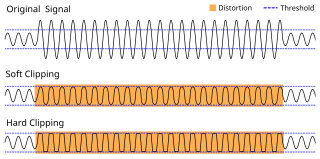
In electronics, a limiter is a circuit that allows signals below a specified input power or level to pass unaffected while attenuating (lowering) the peaks of stronger signals that exceed this threshold. Limiting is a type of dynamic range compression. Clipping is an extreme version of limiting.

<span class="mw-page-title-main">Voltage-controlled oscillator</span> Oscillator with frequency controlled by a voltage input

A voltage-controlled oscillator (VCO) is an electronic oscillator whose oscillation frequency is controlled by a voltage input. The applied input voltage determines the instantaneous oscillation frequency. Consequently, a VCO can be used for frequency modulation (FM) or phase modulation (PM) by applying a modulating signal to the control input. A VCO is also an integral part of a phase-locked loop. VCOs are used in synthesizers to generate a waveform whose pitch can be adjusted by a voltage determined by a musical keyboard or other input.

A radio transmitter or just transmitter is an electronic device which produces radio waves with an antenna. Radio waves are electromagnetic waves with frequencies between about 30 Hz and 300 GHz. The transmitter itself generates a radio frequency alternating current, which is applied to the antenna. When excited by this alternating current, the antenna radiates radio waves. Transmitters are necessary parts of all systems that use radio: radio and television broadcasting, cell phones, wireless networks, radar, two way radios like walkie talkies, radio navigation systems like GPS, remote entry systems, among numerous other uses.

Radio receiver design includes the electronic design of different components of a radio receiver which processes the radio frequency signal from an antenna in order to produce usable information such as audio. The complexity of a modern receiver and the possible range of circuitry and methods employed are more generally covered in electronics and communications engineering. The term radio receiver is understood in this article to mean any device which is intended to receive a radio signal in order to generate useful information from the signal, most notably a recreation of the so-called baseband signal which modulated the radio signal at the time of transmission in a communications or broadcast system.

In electronics, motorboating is a type of low frequency parasitic oscillation that sometimes occurs in audio and radio equipment and often manifests itself as a sound similar to an idling motorboat engine, a "put-put-put", in audio output from speakers or earphones. It is a problem encountered particularly in radio transceivers and older vacuum tube audio systems, guitar amplifiers, PA systems and is caused by some type of unwanted feedback in the circuit. The amplifying devices in audio and radio equipment are vulnerable to a variety of feedback problems, which can cause distinctive noise in the output. The term motorboating is applied to oscillations whose frequency is below the range of hearing, from 1 to 10 hertz, so the individual oscillations are heard as pulses. Sometimes the oscillations can even be seen visually as the woofer cones in speakers slowly moving in and out.

<span class="mw-page-title-main">Detector (radio)</span> Device which extracts info from a modulated radio frequency current or voltage

In radio, a detector is a device or circuit that extracts information from a modulated radio frequency current or voltage. The term dates from the first three decades of radio (1888-1918). Unlike modern radio stations which transmit sound on an uninterrupted carrier wave, early radio stations transmitted information by radiotelegraphy. The transmitter was switched on and off to produce long or short periods of radio waves, spelling out text messages in Morse code. Therefore, early radio receivers did not have to demodulate the radio signal, but just distinguish between the presence or absence of a radio signal, to reproduce the Morse code "dots" and "dashes". The device that performed this function in the receiver circuit was called a detector. A variety of different detector devices, such as the coherer, electrolytic detector, magnetic detector and the crystal detector, were used during the wireless telegraphy era until superseded by vacuum tube technology.

<span class="mw-page-title-main">Reflex receiver</span>

A reflex radio receiver, occasionally called a reflectional receiver, is a radio receiver design in which the same amplifier is used to amplify the high-frequency radio signal (RF) and low-frequency audio (sound) signal (AF). It was first invented in 1914 by German scientists Wilhelm Schloemilch and Otto von Bronk, and rediscovered and extended to multiple tubes in 1917 by Marius Latour and William H. Priess. The radio signal from the antenna and tuned circuit passes through an amplifier, is demodulated in a detector which extracts the audio signal from the radio carrier, and the resulting audio signal passes again through the same amplifier for audio amplification before being applied to the earphone or loudspeaker. The reason for using the amplifier for "double duty" was to reduce the number of active devices, vacuum tubes or transistors, required in the circuit, to reduce the cost. The economical reflex circuit was used in inexpensive vacuum tube radios in the 1920s, and was revived again in simple portable tube radios in the 1930s.

A radar system uses a radio-frequency electromagnetic signal reflected from a target to determine information about that target. In any radar system, the signal transmitted and received will exhibit many of the characteristics described below.

<span class="mw-page-title-main">Plate detector (radio)</span>

In electronics, a plate detector is a vacuum tube circuit in which an amplifying tube having a control grid is operated in a non-linear region of its grid voltage versus plate current transfer characteristic, usually near plate current cutoff, to demodulate amplitude modulated carrier signal. This differs from the grid leak detector, which utilizes the non-linearity of the grid voltage versus grid current characteristic for demodulation. It also differs from the diode detector, which is a two-terminal device.

An RF chain is a cascade of electronic components and sub-units which may include amplifiers, filters, mixers, attenuators and detectors. It can take many forms, for example, as a wide-band receiver-detector for electronic warfare (EW) applications, as a tunable narrow-band receiver for communications purposes, as a repeater in signal distribution systems, or as an amplifier and up-converters for a transmitter-driver. In this article, the term RF covers the frequency range "Medium Frequencies" up to "Microwave Frequencies", i.e. from 100 kHz to 20 GHz.

References

  1. K. Küpfmüller, "Über die Dynamik der selbsttätigen Verstärkungsregler", Elektrische Nachrichtentechnik, vol. 5, no. 11, pp. 459-467, 1928. (German) On the dynamics of automatic gain controllers, (English translation)
  2. Memorial Tributes: National Academy of Engineering, Volume 9 (2001) page 281, retrieved 2009 Oct 23
  3. F. Langford-Smith (ed.), Radiotron Designer's Handbook 4th ed., RCA, 1953, chapter 27 section 3
  4. Automatic gain control in receivers by Iulian Rosu, VA3IUL
  5. Langford-Smith 53, page 1108
  6. Langford-Smith 53, chapter 25 page 1229
  7. Vogad at Federal Standard 1037C
  8. "Roar and Whisper Equalled by Radio Voice Leveler". Popular Mechanics: 236. Feb 1939.
  9. D. O. Kim (1984). "Functional roles of the inner-and outer-hair-cell subsystems in the cochlea and brainstem". In C. I. Berlin (ed.). Hearing science: Recent advances (PDF). College Hill Press. pp. 241–262. Archived from the original (PDF) on 2010-07-01. Retrieved 2010-10-13.
  10. R. F. Lyon (1990). "Automatic Gain Control in Cochlear Mechanics". In P. Dallos; et al. (eds.). The Mechanics and Biophysics of Hearing (PDF). Springer-Verlag. pp. 395–402.[ permanent dead link ]