
A multivibrator is an electronic circuit used to implement a variety of simple two-state devices such as relaxation oscillators, timers and flip-flops. It consists of two amplifying devices cross-coupled by resistors or capacitors. The first multivibrator circuit, the astable multivibrator oscillator, was invented by Henri Abraham and Eugene Bloch during World War I. They called their circuit a "multivibrator" because its output waveform was rich in harmonics.

An operational amplifier is a DC-coupled high-gain electronic voltage amplifier with a differential input and, usually, a single-ended output. In this configuration, an op amp produces an output potential that is typically 100,000 times larger than the potential difference between its input terminals. Operational amplifiers had their origins in analog computers, where they were used to perform mathematical operations in many linear, non-linear, and frequency-dependent circuits.

A bipolar junction transistor (BJT) is a type of transistor that uses both electrons and holes as charge carriers. Unipolar transistors, such as field-effect transistors, use only one kind of charge carrier. A bipolar transistor allows a small current injected at one of its terminals to control a much larger current flowing between two other terminals, making the device capable of amplification or switching.

A Zener diode is a special type of diode designed to reliably allow current to flow "backwards" when a certain set reverse voltage, known as the Zener voltage, is reached.

In electronics, a multi-transistor configuration called the Darlington configuration is a compound structure of a particular design made by two bipolar transistors connected in such a way that the current amplified by the first transistor is amplified further by the second one. This configuration gives a much higher current gain than each transistor taken separately. It was invented in 1953 by Sidney Darlington.
In electronics, a linear regulator is a system used to maintain a steady voltage. The resistance of the regulator varies in accordance with both the input voltage and the load, resulting in a constant voltage output. The regulating device is made to act like a variable resistor, continuously adjusting a voltage divider network to maintain a constant output voltage and continually dissipating the difference between the input and regulated voltages as waste heat. By contrast, a switching regulator uses an active device that switches on and off to maintain an average value of output. Because the regulated voltage of a linear regulator must always be lower than input voltage, efficiency is limited and the input voltage must be high enough to always allow the active device to drop some voltage.

The silicon bandgap temperature sensor is an extremely common form of temperature sensor (thermometer) used in electronic equipment. Its main advantage is that it can be included in a silicon integrated circuit at very low cost. The principle of the sensor is that the forward voltage of a silicon diode, which may be the base-emitter junction of a bipolar junction transistor (BJT), is temperature-dependent, according to the following equation:

A differential amplifier is a type of electronic amplifier that amplifies the difference between two input voltages but suppresses any voltage common to the two inputs. It is an analog circuit with two inputs and and one output in which the output is ideally proportional to the difference between the two voltages

In electronics, a Schmitt trigger is a comparator circuit with hysteresis implemented by applying positive feedback to the noninverting input of a comparator or differential amplifier. It is an active circuit which converts an analog input signal to a digital output signal. The circuit is named a "trigger" because the output retains its value until the input changes sufficiently to trigger a change. In the non-inverting configuration, when the input is higher than a chosen threshold, the output is high. When the input is below a different (lower) chosen threshold the output is low, and when the input is between the two levels the output retains its value. This dual threshold action is called hysteresis and implies that the Schmitt trigger possesses memory and can act as a bistable multivibrator. There is a close relation between the two kinds of circuits: a Schmitt trigger can be converted into a latch and a latch can be converted into a Schmitt trigger.
A bandgap voltage reference is a temperature independent voltage reference circuit widely used in integrated circuits. It produces a fixed (constant) voltage regardless of power supply variations, temperature changes and circuit loading from a device. It commonly has an output voltage around 1.25 V. This circuit concept was first published by David Hilbiber in 1964. Bob Widlar, Paul Brokaw and others followed up with other commercially successful versions.
A current mirror is a circuit designed to copy a current through one active device by controlling the current in another active device of a circuit, keeping the output current constant regardless of loading. The current being "copied" can be, and sometimes is, a varying signal current. Conceptually, an ideal current mirror is simply an ideal inverting current amplifier that reverses the current direction as well. Or it can consist of a current-controlled current source (CCCS). The current mirror is used to provide bias currents and active loads to circuits. It can also be used to model a more realistic current source.

A current source is an electronic circuit that delivers or absorbs an electric current which is independent of the voltage across it.
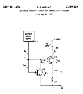
A Widlar current source is a modification of the basic two-transistor current mirror that incorporates an emitter degeneration resistor for only the output transistor, enabling the current source to generate low currents using only moderate resistor values.
A voltage reference is an electronic device that ideally produces a fixed (constant) voltage irrespective of the loading on the device, power supply variations, temperature changes, and the passage of time. Voltage references are used in power supplies, analog-to-digital converters, digital-to-analog converters, and other measurement and control systems. Voltage references vary widely in performance; a regulator for a computer power supply may only hold its value to within a few percent of the nominal value, whereas laboratory voltage standards have precisions and stability measured in parts per million.
In electronics, a rubber diode or VBE multiplier is a bipolar junction transistor circuit that serves as a voltage reference. It consists of one transistor and two resistors, and the reference voltage across the circuit is determined by the selected resistor values and the base-to-emitter voltage (VBE) of the transistor. The circuit behaves as a voltage divider, but with the voltage across the base-emitter resistor determined by the forward base-emitter junction voltage.
A Wilson current mirror is a three-terminal circuit that accepts an input current at the input terminal and provides a "mirrored" current source or sink output at the output terminal. The mirrored current is a precise copy of the input current. It may be used as a Wilson current source by applying a constant bias current to the input branch as in Fig. 2. The circuit is named after George R. Wilson, an integrated circuit design engineer who worked for Tektronix. Wilson devised this configuration in 1967 when he and Barrie Gilbert challenged each other to find an improved current mirror overnight that would use only three transistors. Wilson won the challenge.

The LM317 is a popular adjustable positive linear voltage regulator. It was designed by Bob Dobkin in 1976 while he worked at National Semiconductor.

Bipolar transistors must be properly biased to operate correctly. In circuits made with individual devices, biasing networks consisting of resistors are commonly employed. Much more elaborate biasing arrangements are used in integrated circuits, for example, bandgap voltage references and current mirrors. The voltage divider configuration achieves the correct voltages by the use of resistors in certain patterns. By selecting the proper resistor values, stable current levels can be achieved that vary only little over temperature and with transistor properties such as β.
A log amplifier is an amplifier for which the output voltage Vout is K times the natural log of the input voltage Vin. This can be expressed as,
Baker clamp is a generic name for a class of electronic circuits that reduce the storage time of a switching bipolar junction transistor (BJT) by applying a nonlinear negative feedback through various kinds of diodes. The reason for slow turn-off times of saturated BJTs is the stored charge in the base. It must be removed before the transistor will turn off since the storage time is a limiting factor of using bipolar transistors and IGBTs in fast switching applications. The diode-based Baker clamps prevent the transistor from saturating and thereby accumulating a lot of stored charge.
