An amplifier, electronic amplifier or (informally) amp is an electronic device that can increase the magnitude of a signal. It is a two-port electronic circuit that uses electric power from a power supply to increase the amplitude of a signal applied to its input terminals, producing a proportionally greater amplitude signal at its output. The amount of amplification provided by an amplifier is measured by its gain: the ratio of output voltage, current, or power to input. An amplifier is defined as a circuit that has a power gain greater than one.

A power supply is an electrical device that supplies electric power to an electrical load. The main purpose of a power supply is to convert electric current from a source to the correct voltage, current, and frequency to power the load. As a result, power supplies are sometimes referred to as electric power converters. Some power supplies are separate standalone pieces of equipment, while others are built into the load appliances that they power. Examples of the latter include power supplies found in desktop computers and consumer electronics devices. Other functions that power supplies may perform include limiting the current drawn by the load to safe levels, shutting off the current in the event of an electrical fault, power conditioning to prevent electronic noise or voltage surges on the input from reaching the load, power-factor correction, and storing energy so it can continue to power the load in the event of a temporary interruption in the source power.

In electronics, a varicap diode, varactor diode, variable capacitance diode, variable reactance diode or tuning diode is a type of diode designed to exploit the voltage-dependent capacitance of a reverse-biased p–n junction.

The RC time constant, also called tau, the time constant of an RC circuit, is equal to the product of the circuit resistance and the circuit capacitance, i.e.

An electronic component is any basic discrete electronic device or physical entity part of an electronic system used to affect electrons or their associated fields. Electronic components are mostly industrial products, available in a singular form and are not to be confused with electrical elements, which are conceptual abstractions representing idealized electronic components and elements.
In signal processing, when describing a periodic function in the time domain, the DC bias, DC component, DC offset, or DC coefficient is the mean amplitude of the waveform. If the mean amplitude is zero, there is no DC bias. A waveform with no DC bias is known as a DC balanced or DC free waveform.

A variable capacitor is a capacitor whose capacitance may be intentionally and repeatedly changed mechanically or electronically. Variable capacitors are often used in L/C circuits to set the resonance frequency, e.g. to tune a radio, or as a variable reactance, e.g. for impedance matching in antenna tuners.

Capacitors are manufactured in many styles, forms, dimensions, and from a large variety of materials. They all contain at least two electrical conductors, called plates, separated by an insulating layer (dielectric). Capacitors are widely used as parts of electrical circuits in many common electrical devices.

In electronics, a choke is an inductor used to block higher-frequency alternating currents (AC) while passing direct current (DC) and lower-frequency ACs in a circuit. A choke usually consists of a coil of insulated wire often wound on a magnetic core, although some consist of a doughnut-shaped ferrite bead strung on a wire. The choke's impedance increases with frequency. Its low electrical resistance passes both AC and DC with little power loss, but its reactance limits the amount of AC passed.
In electronics, the Miller effect accounts for the increase in the equivalent input capacitance of an inverting voltage amplifier due to amplification of the effect of capacitance between the input and output terminals. The virtually increased input capacitance due to the Miller effect is given by
In electronics, motorboating is a type of low frequency parasitic oscillation that sometimes occurs in audio and radio equipment and often manifests itself as a sound similar to an idling motorboat engine, a "put-put-put", in audio output from speakers or earphones. It is a problem encountered particularly in radio transceivers and older vacuum tube audio systems, guitar amplifiers, PA systems and is caused by some type of unwanted feedback in the circuit. The amplifying devices in audio and radio equipment are vulnerable to a variety of feedback problems, which can cause distinctive noise in the output. The term motorboating is applied to oscillations whose frequency is below the range of hearing, from 1 to 10 hertz, so the individual oscillations are heard as pulses. Sometimes the oscillations can even be seen visually as the woofer cones in speakers slowly moving in and out.
Parasitic capacitance is an unavoidable and usually unwanted capacitance that exists between the parts of an electronic component or circuit simply because of their proximity to each other. When two electrical conductors at different voltages are close together, the electric field between them causes electric charge to be stored on them; this effect is capacitance.

In electronics, noise is an unwanted disturbance in an electrical signal.
In electronics, direct coupling or DC coupling is the transfer of electrical energy by means of physical contact via a conductive medium, in contrast to inductive coupling and capacitive coupling. It is a way of interconnecting two circuits such that, in addition to transferring the AC signal, the first circuit also provides DC bias to the second. Thus, DC blocking capacitors are not used or needed to interconnect the circuits. Conductive coupling passes the full spectrum of frequencies including direct current.

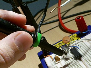
A test probe is a physical device used to connect electronic test equipment to a device under test (DUT). Test probes range from very simple, robust devices to complex probes that are sophisticated, expensive, and fragile. Specific types include test prods, oscilloscope probes and current probes. A test probe is often supplied as a test lead, which includes the probe, cable and terminating connector.

A clamper is an electronic circuit that fixes either the positive or the negative peak excursions of a signal to a defined voltage by adding a variable positive or negative DC voltage to it. The clamper does not restrict the peak-to-peak excursion of the signal (clipping); it moves the whole signal up or down so as to place its peaks at the reference level.

A multistage amplifier is an electronic amplifier consisting of two or more single-stage amplifiers connected together. In this context, a single stage is an amplifier containing only a single transistor or other active device. The most common reason for using multiple stages is to increase the gain of the amplifier in applications where the input signal is very small, for instance in radio receivers. In these applications a single stage has insufficient gain by itself. In some designs it is possible to obtain more desirable values of other parameters such as input resistance and output resistance.

A ceramic capacitor is a fixed-value capacitor where the ceramic material acts as the dielectric. It is constructed of two or more alternating layers of ceramic and a metal layer acting as the electrodes. The composition of the ceramic material defines the electrical behavior and therefore applications. Ceramic capacitors are divided into two application classes:
In electrical engineering, capacitive sensing is a technology, based on capacitive coupling, that can detect and measure anything that is conductive or has a dielectric constant different from air. Many types of sensors use capacitive sensing, including sensors to detect and measure proximity, pressure, position and displacement, force, humidity, fluid level, and acceleration. Human interface devices based on capacitive sensing, such as touchpads, can replace the computer mouse. Digital audio players, mobile phones, and tablet computers will sometimes use capacitive sensing touchscreens as input devices. Capacitive sensors can also replace mechanical buttons.

Capacitors have many uses in electronic and electrical systems. They are so ubiquitous that it is rare that an electrical product does not include at least one for some purpose. Capacitors allow only AC signals to pass when they are charged blocking DC signals. The main components of filters are capacitors. Capacitors have the ability to connect one circuit segment to another. Capacitors are used by Dynamic Random Access Memory (DRAM) devices to represent binary information as bits.


