A galvanometer is an electromechanical measuring instrument for electric current. Early galvanometers were uncalibrated, but improved versions, called ammeters, were calibrated and could measure the flow of current more precisely.

A drawing board is, in its antique form, a kind of multipurpose desk which can be used for any kind of drawing, writing or impromptu sketching on a large sheet of paper or for reading a large format book or other oversized document or for drafting precise technical illustrations. The drawing table used to be a frequent companion to a pedestal desk in a study or private library, during the pre-industrial and early industrial era.

In geometry, straightedge-and-compass construction – also known as ruler-and-compass construction, Euclidean construction, or classical construction – is the construction of lengths, angles, and other geometric figures using only an idealized ruler and a pair of compasses.

Angle trisection is a classical problem of straightedge and compass construction of ancient Greek mathematics. It concerns construction of an angle equal to one third of a given arbitrary angle, using only two tools: an unmarked straightedge and a compass.

An engineering drawing is a type of technical drawing that is used to convey information about an object. A common use is to specify the geometry necessary for the construction of a component and is called a detail drawing. Usually, a number of drawings are necessary to completely specify even a simple component. The drawings are linked together by a master drawing or assembly drawing which gives the drawing numbers of the subsequent detailed components, quantities required, construction materials and possibly 3D images that can be used to locate individual items. Although mostly consisting of pictographic representations, abbreviations and symbols are used for brevity and additional textual explanations may also be provided to convey the necessary information.

A nephoscope is a 19th-century instrument for measuring the altitude, direction, and velocity of clouds, using transit-time measurement. This is different from a nephometer, which is an instrument used in measuring the amount of cloudiness.

Caliper(s) or calliper(s) are an instrument used to measure the dimensions of an object; namely, the diameter or depth of a hole. The least count of vernier caliper is 0.1 mm.

A milliradian is an SI derived unit for angular measurement which is defined as a thousandth of a radian (0.001 radian). Milliradians are used in adjustment of firearm sights by adjusting the angle of the sight compared to the barrel. Milliradians are also used for comparing shot groupings, or to compare the difficulty of hitting different sized shooting targets at different distances. When using a scope with both mrad adjustment and a reticle with mrad markings, the shooter can use the reticle as a ruler to count the number of mrads a shot was off-target, which directly translates to the sight adjustment needed to hit the target with a follow-up shot. Optics with mrad markings in the reticle can also be used to make a range estimation of a known size target, or vice versa, to determine a target size if the distance is known, a practice called "milling".
Marking out or layout means the process of transferring a design or pattern to a workpiece, as the first step in the manufacturing process. It is performed in many industries or hobbies although in the repetition industries the machine's initial setup is designed to remove the need to mark out every individual piece.

A vise or vice is a mechanical apparatus used to secure an object to allow work to be performed on it. Vises have two parallel jaws, one fixed and the other movable, threaded in and out by a screw and lever.

A spherometer is an instrument used for the precise measurement of the radius of curvature of a curved surface. Originally, these instruments were primarily used by opticians to measure the curvature of the surface of a lens.

A ball screw is a mechanical linear actuator that translates rotational motion to linear motion with little friction. A threaded shaft provides a helical raceway for ball bearings which act as a precision screw. As well as being able to apply or withstand high thrust loads, they can do so with minimum internal friction. They are made to close tolerances and are therefore suitable for use in situations in which high precision is necessary. The ball assembly acts as the nut while the threaded shaft is the screw.
The sector, also known as a proportional compass or military compass, was a major calculating instrument in use from the end of the sixteenth century until the nineteenth century. It is an instrument consisting of two rulers of equal length joined by a hinge. A number of scales are inscribed upon the instrument which facilitate various mathematical calculations. It was used for solving problems in proportion, multiplication and division, geometry, and trigonometry, and for computing various mathematical functions, such as square roots and cube roots. Its several scales permitted easy and direct solutions of problems in gunnery, surveying and navigation. The sector derives its name from the fourth proposition of the sixth book of Euclid, where it is demonstrated that similar triangles have their like sides proportional. Some sectors also incorporated a quadrant, and sometimes a clamp at the end of one leg which allowed the device to be used as a gunner's quadrant.

Tune-o-matic is the name of a fixed or floating bridge design for electric guitars. It was designed by Ted McCarty and introduced on the Gibson Super 400 guitar in 1953 and the Les Paul Custom the following year. In 1955, it was used on the Gibson Les Paul Gold Top. It was gradually accepted as a standard on almost all Gibson electric guitars, replacing the previous wrap-around bridge design, except on the budget series.
A beam compass is a compass with a beam and sliding sockets or cursors for drawing and dividing circles larger than those made by a regular pair of compasses. The instrument can be as a whole, or made on the spot with individual sockets and any suitable beam.

In mechanical engineering, backlash, sometimes called lash, play, or slop, is a clearance or lost motion in a mechanism caused by gaps between the parts. It can be defined as "the maximum distance or angle through which any part of a mechanical system may be moved in one direction without applying appreciable force or motion to the next part in mechanical sequence."p. 1-8 An example, in the context of gears and gear trains, is the amount of clearance between mated gear teeth. It can be seen when the direction of movement is reversed and the slack or lost motion is taken up before the reversal of motion is complete. It can be heard from the railway couplings when a train reverses direction. Another example is in a valve train with mechanical tappets, where a certain range of lash is necessary for the valves to work properly.

Drafting tools may be used for measurement and layout of drawings, or to improve the consistency and speed of creation of standard drawing elements. Tools such as pens and pencils mark the drawing medium. Other tools such as straight edges, assist the operator in drawing straight lines, or assist the operator in drawing complicated shapes repeatedly. Various scales and the protractor are used to measure the lengths of lines and angles, allowing accurate scale drawing to be carried out. The compass is used to draw arcs and circles. A drawing board was used to hold the drawing media in place; later boards included drafting machines that sped the layout of straight lines and angles. Tools such as templates and lettering guides assisted in the drawing of repetitive elements such as circles, ellipses, schematic symbols and text. Other auxiliary tools were used for special drawing purposes or for functions related to the preparation and revision of drawings. The tools used for manual technical drawing have been displaced by the advent of computer-aided drawing, drafting and design (CADD).

A trammel of Archimedes is a mechanism that generates the shape of an ellipse. It consists of two shuttles which are confined ("trammeled") to perpendicular channels or rails and a rod which is attached to the shuttles by pivots at fixed positions along the rod.
A cyclograph is an instrument for drawing arcs of large diameter circles whose centres are inconveniently or inaccessibly located, one version of which was invented by Scottish architect and mathematician Peter Nicholson.
Geometric Constructions is a mathematics textbook on constructible numbers, and more generally on using abstract algebra to model the sets of points that can be created through certain types of geometric construction, and using Galois theory to prove limits on the constructions that can be performed. It was written by George E. Martin, and published by Springer-Verlag in 1998 as volume 81 of their Undergraduate Texts in Mathematics book series.
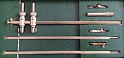 Keuffel & Esser Arrow beam compass set for drafting.
 18th-century ellipse-drawing compass (MHS Geneva)
 Simple reduction compass (MHS Geneva).
 Sliding-pivot reduction compass by Nairne on London, 18th century (MHS Geneva).