
A logic gate is a device that performs a Boolean function, a logical operation performed on one or more binary inputs that produces a single binary output. Depending on the context, the term may refer to an ideal logic gate, one that has, for instance, zero rise time and unlimited fan-out, or it may refer to a non-ideal physical device.
NMOS or nMOS logic uses n-type (-) MOSFETs to implement logic gates and other digital circuits.
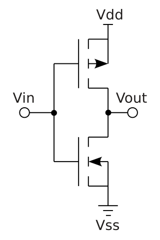
Complementary metal–oxide–semiconductor is a type of metal–oxide–semiconductor field-effect transistor (MOSFET) fabrication process that uses complementary and symmetrical pairs of p-type and n-type MOSFETs for logic functions. CMOS technology is used for constructing integrated circuit (IC) chips, including microprocessors, microcontrollers, memory chips, and other digital logic circuits. CMOS technology is also used for analog circuits such as image sensors, data converters, RF circuits, and highly integrated transceivers for many types of communication.

In electronics and especially synchronous digital circuits, a clock signal is an electronic logic signal which oscillates between a high and a low state at a constant frequency and is used like a metronome to synchronize actions of digital circuits. In a synchronous logic circuit, the most common type of digital circuit, the clock signal is applied to all storage devices, flip-flops and latches, and causes them all to change state simultaneously, preventing race conditions.

The 4000 series is a CMOS logic family of integrated circuits (ICs) first introduced in 1968 by RCA. It was slowly migrated into the 4000B buffered series after about 1975. It had a much wider supply voltage range than any contemporary logic family. Almost all IC manufacturers active during this initial era fabricated models for this series. Its naming convention is still in use today.
In digital electronics, the fan-out is the number of gate inputs driven by the output of another single logic gate.

A barrel shifter is a digital circuit that can shift a data word by a specified number of bits without the use of any sequential logic, only pure combinational logic, i.e. it inherently provides a binary operation. It can however in theory also be used to implement unary operations, such as logical shift left, in cases where limited by a fixed amount. One way to implement a barrel shifter is as a sequence of multiplexers where the output of one multiplexer is connected to the input of the next multiplexer in a way that depends on the shift distance. A barrel shifter is often used to shift and rotate n-bits in modern microprocessors, typically within a single clock cycle.
The method of logical effort, a term coined by Ivan Sutherland and Bob Sproull in 1991, is a straightforward technique used to estimate delay in a CMOS circuit. Used properly, it can aid in selection of gates for a given function and sizing gates to achieve the minimum delay possible for a circuit.
An adder, or summer, is a digital circuit that performs addition of numbers. In many computers and other kinds of processors, adders are used in the arithmetic logic units (ALUs). They are also used in other parts of the processor, where they are used to calculate addresses, table indices, increment and decrement operators and similar operations.
In Boolean algebra, any Boolean function can be expressed in the canonical disjunctive normal form (CDNF) or minterm canonical form, and its dual, the canonical conjunctive normal form (CCNF) or maxterm canonical form. Other canonical forms include the complete sum of prime implicants or Blake canonical form, and the algebraic normal form.
In digital circuit design, register-transfer level (RTL) is a design abstraction which models a synchronous digital circuit in terms of the flow of digital signals (data) between hardware registers, and the logical operations performed on those signals.
In computer engineering, a logic family is one of two related concepts:
Propagation delay is the time duration taken for a signal to reach its destination. It can relate to networking, electronics or physics.
A carry-lookahead adder (CLA) or fast adder is a type of electronics adder used in digital logic. A carry-lookahead adder improves speed by reducing the amount of time required to determine carry bits. It can be contrasted with the simpler, but usually slower, ripple-carry adder (RCA), for which the carry bit is calculated alongside the sum bit, and each stage must wait until the previous carry bit has been calculated to begin calculating its own sum bit and carry bit. The carry-lookahead adder calculates one or more carry bits before the sum, which reduces the wait time to calculate the result of the larger-value bits of the adder.
A carry-skip adder is an adder implementation that improves on the delay of a ripple-carry adder with little effort compared to other adders. The improvement of the worst-case delay is achieved by using several carry-skip adders to form a block-carry-skip adder.

In integrated circuits, depletion-load NMOS is a form of digital logic family that uses only a single power supply voltage, unlike earlier NMOS logic families that needed more than one different power supply voltage. Although manufacturing these integrated circuits required additional processing steps, improved switching speed and the elimination of the extra power supply made this logic family the preferred choice for many microprocessors and other logic elements.
XOR gate is a digital logic gate that gives a true output when the number of true inputs is odd. An XOR gate implements an exclusive or from mathematical logic; that is, a true output results if one, and only one, of the inputs to the gate is true. If both inputs are false (0/LOW) or both are true, a false output results. XOR represents the inequality function, i.e., the output is true if the inputs are not alike otherwise the output is false. A way to remember XOR is "must have one or the other but not both".
In integrated circuit design, dynamic logic is a design methodology in combinational logic circuits, particularly those implemented in metal–oxide–semiconductor (MOS) technology. It is distinguished from the so-called static logic by exploiting temporary storage of information in stray and gate capacitances. It was popular in the 1970s and has seen a recent resurgence in the design of high-speed digital electronics, particularly central processing units (CPUs). Dynamic logic circuits are usually faster than static counterparts and require less surface area, but are more difficult to design. Dynamic logic has a higher average rate of voltage transitions than static logic, but the capacitive loads being transitioned are smaller so the overall power consumption of dynamic logic may be higher or lower depending on various tradeoffs. When referring to a particular logic family, the dynamic adjective usually suffices to distinguish the design methodology, e.g. dynamic CMOS or dynamic SOI design.
Four-phase logic is a type of, and design methodology for dynamic logic. It enabled non-specialist engineers to design quite complex ICs, using either PMOS or NMOS processes. It uses a kind of 4-phase clock signal.
PMOS or pMOS logic is a family of digital circuits based on p-channel, enhancement mode metal–oxide–semiconductor field-effect transistors (MOSFETs). In the late 1960s and early 1970s, PMOS logic was the dominant semiconductor technology for large-scale integrated circuits before being superseded by NMOS and CMOS devices.