Linear particle accelerator

Last updated
The linac within the Australian Synchrotron uses radio waves from a series of RF cavities at the start of the linac to accelerate the electron beam in bunches to energies of 100 MeV. Aust.-Synchrotron,-Linac,-14.06.2007.jpg
The linac within the Australian Synchrotron uses radio waves from a series of RF cavities at the start of the linac to accelerate the electron beam in bunches to energies of 100 MeV.

A linear particle accelerator (often shortened to linac) is a type of particle accelerator that accelerates charged subatomic particles or ions to a high speed by subjecting them to a series of oscillating electric potentials along a linear beamline. The principles for such machines were proposed by Gustav Ising in 1924, [1] while the first machine that worked was constructed by Rolf Widerøe in 1928 [2] at the RWTH Aachen University. [3] [4] Linacs have many applications: they generate X-rays and high energy electrons for medicinal purposes in radiation therapy, serve as particle injectors for higher-energy accelerators, and are used directly to achieve the highest kinetic energy for light particles (electrons and positrons) for particle physics.

Contents

The design of a linac depends on the type of particle that is being accelerated: electrons, protons or ions. Linacs range in size from a cathode ray tube (which is a type of linac) to the 3.2-kilometre-long (2.0 mi) linac at the SLAC National Accelerator Laboratory in Menlo Park, California.

History

Wideroe's linac concept. The voltage from an RF source is connected to a series of tubes which shield the particle between gaps. Wideroe linac en.svg
Wideroe's linac concept. The voltage from an RF source is connected to a series of tubes which shield the particle between gaps.
Alvarez type linac CERN Linac1.jpg
Alvarez type linac

In 1924, Gustav Ising published the first description of a linear particle accelerator using a series of accelerating gaps. Particles would proceed down a series of tubes. At a regular frequency, an accelerating voltage would be applied across each gap. As the particles gained speed while the frequency remained constant, the gaps would be spaced farther and farther apart, in order to ensure the particle would see a voltage applied as it reached each gap. Ising never successfully implemented this design. [5]

Rolf Wideroe discovered Ising's paper in 1927, and as part of his PhD thesis, built an 88-inch long, two gap version of the device. Where Ising had proposed a spark gap as the voltage source, Wideroe used a 25kV vacuum tube oscillator. He successfully demonstrated that he had accelerated sodium and potassium ions to an energy of 50 thousand electron volts (50 keV), twice the energy they would have received if accelerated only once by the tube. By successfully accelerating a particle multiple times using the same voltage source, Wideroe demonstrated the utility of radio frequency acceleration. [6]

This type of linac was limited by the voltage sources that were available at the time, and it was not until after World War II that Luis Alvarez was able to use newly developed high frequency oscillators to design the first resonant cavity drift tube linac. An Alvarez linac differs from the Wideroe type in that the RF power is applied to the entire resonant chamber through which the particle travels, and the central tubes are only used to shield the particles during the decelerating portion of the oscillator's phase. Using this approach to acceleration meant that Alvarez's first linac was able to achieve proton energies of 31.5 MeV in 1947, the highest that had ever been reached at the time. [7]

The initial Alvarez type linacs had no strong mechanism for keeping the beam focused, and were limited in length and energy as a result. The development of the strong focusing principle in the early 1950s led to the installation of focusing quadrupole magnets inside the drift tubes, allowing for longer and thus more powerful linacs. Two of the earliest examples of Alvarez linacs with strong focusing magnets were built at CERN and Brookhaven National Laboratory. [8]

In 1947, at about the same time that Alvarez was developing his linac concept for protons, William Hansen constructed the first travelling-wave electron accelerator at Stanford University. [9] Electrons are sufficiently lighter than protons that they achieve speeds close to the speed of light early in the acceleration process. As a result, "accelerating" electrons increase in energy, but can be treated as having a constant velocity from an accelerator design standpoint. This allowed Hansen to use an accelerating structure consisting of a horizontal waveguide loaded by a series of discs. The 1947 accelerator had an energy of 6 MeV. Over time, electron acceleration at the SLAC National Accelerator Laboratory would extend to a size of 2 miles (3.2 km) and an output energy of 50 GeV. [10]

As linear accelerators were developed with higher beam currents, using magnetic fields to focus proton and heavy ion beams presented difficulties for the initial stages of the accelerator. Because the magnetic force is dependent on the particle velocity, it was desirable to create a type of accelerator which could simultaneously accelerate and focus low-to-mid energy hadrons. [11] In 1970, Soviet physicists I. M. Kapchinsky and Vladimir Teplyakov proposed the radio-frequency quadrupole (RFQ) type of accelerating structure. RFQs use vanes or rods with precisely designed shapes in a resonant cavity to produce complex electric fields. These fields provide simultaneous acceleration and focusing to injected particle beams. [12]

Beginning in the 1960s, scientists at Stanford and elsewhere began to explore the use of superconducting radio frequency cavities for particle acceleration. [13] Superconducting cavities made of niobium alloys allowed for much more efficient acceleration, as a substantially higher fraction of the input power could be applied to the beam, rather than lost to heat. Some of the earliest superconducting linacs included the Superconducting Linear Accelerator (for electrons) at Stanford [14] and the Argonne Tandem Linear Accelerator System (for protons and heavy ions) at Argonne National Laboratory. [15]

Basic principles of operation

Animation showing how a linear accelerator works. In this example the particles accelerated (red dots) are assumed to have a positive charge. The graph V(x) shows the electrical potential along the axis of the accelerator at each point in time. The polarity of the RF voltage reverses as the particle passes through each electrode, so when the particle crosses each gap the electric field (E, arrows) has the correct direction to accelerate it. The animation shows a single particle being accelerated each cycle; in actual linacs a large number of particles are injected and accelerated each cycle. The action is shown slowed enormously. Linear accelerator animation 16frames 1.6sec.gif
Animation showing how a linear accelerator works. In this example the particles accelerated (red dots) are assumed to have a positive charge. The graph V(x) shows the electrical potential along the axis of the accelerator at each point in time. The polarity of the RF voltage reverses as the particle passes through each electrode, so when the particle crosses each gap the electric field (E, arrows) has the correct direction to accelerate it. The animation shows a single particle being accelerated each cycle; in actual linacs a large number of particles are injected and accelerated each cycle. The action is shown slowed enormously.

Radiofrequency acceleration

When a charged particle is placed in an electromagnetic field it experiences a force given by the Lorentz force law:

(in SI units) where is the charge on the particle, is the electric field, is the particle velocity, and is the magnetic field. The cross product in the magnetic field term means that static magnetic fields cannot be used for particle acceleration, as the magnetic force acts perpendicularly to the direction of particle motion. [16]

As electrostatic breakdown limits the maximum constant voltage which can be applied across a gap to produce an electric field, most accelerators use some form of radiofrequency (RF) acceleration. In RF acceleration, the particle traverses a series of accelerating regions, driven by a source of voltage in such a way that the particle sees an accelerating field as it crosses each region. In this type of acceleration, particles must necessarily travel in "bunches" corresponding to the portion of the oscillator's cycle where the electric field is pointing in the intended direction of acceleration. [17]

If a single oscillating voltage source is used to drive a series of gaps, those gaps must be placed increasingly far apart as the speed of the particle increases. This is to ensure that the particle "sees" the same phase of the oscillator's cycle as it reaches each gap. As particles asymptotically approach the speed of light, the gap separation becomes constant - additional applied force increases the energy of the particles, but does not significantly alter their speed. [16] :9-12

Focusing

In order to ensure particles do not escape the accelerator, it is necessary to provide some form of focusing to redirect particles moving away from the central trajectory back towards the intended path. With the discovery of strong focusing, quadrupole magnets are used to actively redirect particles moving away from the reference path. As quadrupole magnets are focusing in one transverse direction and defocusing in the perpendicular direction, it is necessary to use groups of magnets to provide an overall focusing effect in both directions. [16]

Phase stability

Focusing along the direction of travel, also known as phase stability, is an inherent property of RF acceleration. If the particles in a bunch all reach the accelerating region during the rising phase of the oscillating field, then particles which arrive early will see slightly less voltage than the "reference" particle at the center of the bunch. Those particles will therefore receive slightly less acceleration and eventually fall behind the reference particle. Correspondingly, particles which arrive after the reference particle will receive slightly more acceleration, and will catch up to the reference as a result. This automatic correction occurs at each accelerating gap, so the bunch is refocused along the direction of travel each time it is accelerated. [17] :30–52

Construction and operation

Quadrupole magnets surrounding the linac of the Australian Synchrotron are used to help focus the electron beam Aust.-Synchrotron,-Quadrupole-Magnets-of-Linac,-14.06.2007.jpg
Quadrupole magnets surrounding the linac of the Australian Synchrotron are used to help focus the electron beam
Building covering the 2 mile (3.2 km) beam tube of the Stanford Linear Accelerator (SLAC) at Menlo Park, California, the second most powerful linac in the world. It has about 80,000 accelerating electrodes and could accelerate electrons to 50 GeV SLAC National Accelerator Laboratory Aerial 2.png
Building covering the 2 mile (3.2 km) beam tube of the Stanford Linear Accelerator (SLAC) at Menlo Park, California, the second most powerful linac in the world. It has about 80,000 accelerating electrodes and could accelerate electrons to 50  GeV

A linear particle accelerator consists of the following parts:

As shown in the animation, the oscillating voltage applied to alternate cylindrical electrodes has opposite polarity (180° out of phase), so adjacent electrodes have opposite voltages. This creates an oscillating electric field (E) in the gap between each pair of electrodes, which exerts force on the particles when they pass through, imparting energy to them by accelerating them. The particle source injects a group of particles into the first electrode once each cycle of the voltage, when the charge on the electrode is opposite to the charge on the particles. The electrodes are made the correct length so that the accelerating particles take exactly one-half cycle to pass through each electrode. Each time the particle bunch passes through an electrode, the oscillating voltage changes polarity, so when the particles reach the gap between electrodes the electric field is in the correct direction to accelerate them. Therefore, the particles accelerate to a faster speed each time they pass between electrodes; there is little electric field inside the electrodes so the particles travel at a constant speed within each electrode.

The particles are injected at the right time so that the oscillating voltage differential between electrodes is maximum as the particles cross each gap. If the peak voltage applied between the electrodes is volts, and the charge on each particle is elementary charges, the particle gains an equal increment of energy of electron volts when passing through each gap. Thus the output energy of the particles is

electron volts, where is the number of accelerating electrodes in the machine.

At speeds near the speed of light, the incremental velocity increase will be small, with the energy appearing as an increase in the mass of the particles. In portions of the accelerator where this occurs, the tubular electrode lengths will be almost constant. Additional magnetic or electrostatic lens elements may be included to ensure that the beam remains in the center of the pipe and its electrodes. Very long accelerators may maintain a precise alignment of their components through the use of servo systems guided by a laser beam.

Concepts in development

Various new concepts are in development as of 2021. The primary goal is to make linear accelerators cheaper, with better focused beams, higher energy or higher beam current.

Induction linear accelerator

Induction linear accelerators use the electric field induced by a time-varying magnetic field for acceleration - like the betatron. The particle beam passes through a series of ring-shaped ferrite cores standing one behind the other, which are magnetized by high-current pulses and in turn each generate an electrical field strength pulse along the axis of the beam direction. Induction linear accelerators are considered for short high current pulses from electrons, but also from heavy ions. [22] The concept goes back to the work of Nicholas Christofilos. [23] Its realization is highly dependent on progress in the development of more suitable Ferrite materials. With electrons, pulse currents of up to 5 kiloamps at energies up to 5 MeV and pulse durations in the range of 20 to 300 nanoseconds were achieved. [24]

Energy Recovery LINAC

In previous electron linear accelerators, the accelerated particles are used only once and then fed into an absorber (beam dump), in which their residual energy is converted into heat. In an Energy Recovery Linac (ERL; literally: "Energy recovery linear accelerator"), instead, the accelerated in resonators and, for example, in undulators. The electrons used are fed back through the accelerator, out of phase by 180 degrees. They therefore pass through the resonators in the decelerating phase and thus return their remaining energy to the field. The concept is comparable to the hybrid drive of motor vehicles, where the kinetic energy released during braking is made available for the next acceleration by charging a battery.

The Brookhaven National Laboratory  and the Helmholtz-Zentrum Berlin with the project "bERLinPro"  reported on corresponding development work . The Berlin experimental accelerator uses superconducting niobium cavity resonators of the type mentioned above. In 2014, three free-electron lasers based on Energy Recovery Linacs were in operation worldwide : in the Jefferson Lab (USA), in the Budker Institute of Nuclear Physics (Russia) and at JAEA (Japan). [25]  At the University of Mainz , an ERL called MESA is under construction and should (as of 2019) go into operation in 2022.

Compact Linear Collider

The concept of the Compact Linear Collider (CLIC) (original name CERN Linear Collider , with the same abbreviation) for electrons and positrons provides a traveling wave accelerator for energies of the order of 1 tera-electron volt (TeV). [26] Instead of the otherwise necessary numerous klystron amplifiers to generate the acceleration power, a second, parallel electron linear accelerator of lower energy is to be used, which works with superconducting cavities in which standing waves are formed. High-frequency power is extracted from it at regular intervals and transmitted to the main accelerator. In this way, the very high acceleration field strength of 80 MV / m should be achieved.

Kielfeld accelerator (plasma accelerator)

In cavity resonators, the dielectric strength limits the maximum acceleration that can be achieved within a certain distance. This limit can be circumvented using accelerated waves in plasma to generate the accelerating field in Kielfeld accelerators: A laser or particle beam excites an oscillation in a plasma, which is associated with very strong electric field strengths. This means that significantly (factors of 100s to 1000s ) more compact linear accelerators can possibly be built. Experiments involving high power lasers in metal vapour plasmas suggest that a beam line length reduction from some tens of metres to a few cm is quite possible.

Compact Medical Accelerators

The LIGHT program (Linac for Image-Guided Hadron Therapy) hopes to create a design capable of accelerating protons to 200MeV or so for medical use over a distance of a few tens of metres, by optimising and nesting existing accelerator techniques [27] The current design (2020) uses the highest practical bunch frequency (currently ~ 3 GHz) for a Radio-frequency quadrupole (RFQ) stage from injection at 50kVdC to ~5MeV bunches, a Side Coupled Drift Tube Linac (SCDTL) to accelerate from 5Mev to ~ 40MeV and a Cell Coupled Linac (CCL) stage final, taking the output to 200-230MeV. Each stage is optimised to allow close coupling and synchronous operation during the beam energy build-up. The project aim is to make proton therapy a more accessible mainstream medicine as an alternative to existing radio therapy.

Modern linear accelerator concepts

The higher the frequency of the acceleration voltage selected, the more individual acceleration thrusts per path length a particle of a given speed experiences, and the shorter the accelerator can therefore be overall. That is why accelerator technology developed in the pursuit of higher particle energies, especially towards higher frequencies.

The linear accelerator concepts (often called accelerator structures in technical terms) that have been used since around 1950 work with frequencies in the range from around 100MHz to a few gigahertz (GHz) and use the electric field component of electromagnetic waves.

Standing waves and traveling waves

When it comes to energies of more than a few MeV, accelerators for ions are different from those for electrons. The reason for this is the large mass difference between the particles. Electrons are already close to the speed of light, the absolute speed limit, at a few MeV; with further acceleration, as described by relativistic mechanics, almost only their energy and momentum increase. On the other hand, with ions of this energy range, the speed also increases significantly due to further acceleration.

The acceleration concepts used today for ions are always based on electromagnetic standing waves that are formed in suitable resonators. Depending on the type of particle, energy range and other parameters, very different types of resonators are used; the following sections only cover some of them. Electrons can also be accelerated with standing waves above a few MeV. An advantageous alternative here, however, is a progressive wave, a traveling wave. The phase velocity the traveling wave must be roughly equal to the particle speed. Therefore, this technique is only suitable when the particles are almost at the speed of light, so that their speed only increases very little.

The development of high-frequency oscillators and power amplifiers from the 1940s, especially the klystron, was essential for these two acceleration techniques . The first larger linear accelerator with standing waves - for protons - was built in 1945/46 in the Lawrence Berkeley National Laboratory under the direction of Luis W. Alvarez. The frequency used was 200MHz.  The first electron accelerator with traveling waves of around 2GHz was developed a little later at Stanford University by W.W. Hansen and colleagues. [28]

Principle of the acceleration of particle packets
by a standing wave Linac schematic (standing wave).gif
by a standing wave
by a traveling wave Linac schematic (travelling wave).gif
by a traveling wave

In the two diagrams, the curve and arrows indicate the force acting on the particles. Only at the points with the correct direction of the electric field vector, i.e. the correct direction of force, can particles absorb energy from the wave. (An increase in speed cannot be seen in the scale of these images.)

Advantages

The Stanford University superconducting linear accelerator, housed on campus below the Hansen Labs until 2007. This facility is separate from SLAC Stanford SCA July 1995 16a.jpg
The Stanford University superconducting linear accelerator, housed on campus below the Hansen Labs until 2007. This facility is separate from SLAC
Steel casting undergoing x-ray using the linear accelerator at Goodwin Steel Castings Ltd Linear Accelerator.jpg
Steel casting undergoing x-ray using the linear accelerator at Goodwin Steel Castings Ltd

The linear accelerator could produce higher particle energies than the previous electrostatic particle accelerators (the Cockcroft-Walton accelerator and Van de Graaff generator) that were in use when it was invented. In these machines, the particles were only accelerated once by the applied voltage, so the particle energy in electron volts was equal to the accelerating voltage on the machine, which was limited to a few million volts by insulation breakdown. In the linac, the particles are accelerated multiple times by the applied voltage, so the particle energy is not limited by the accelerating voltage.

High power linacs are also being developed for production of electrons at relativistic speeds, required since fast electrons traveling in an arc will lose energy through synchrotron radiation; this limits the maximum power that can be imparted to electrons in a synchrotron of given size. Linacs are also capable of prodigious output, producing a nearly continuous stream of particles, whereas a synchrotron will only periodically raise the particles to sufficient energy to merit a "shot" at the target. (The burst can be held or stored in the ring at energy to give the experimental electronics time to work, but the average output current is still limited.) The high density of the output makes the linac particularly attractive for use in loading storage ring facilities with particles in preparation for particle to particle collisions. The high mass output also makes the device practical for the production of antimatter particles, which are generally difficult to obtain, being only a small fraction of a target's collision products. These may then be stored and further used to study matter-antimatter annihilation.

Medical linacs

Historical image showing Gordon Isaacs, the first patient treated for retinoblastoma with linear accelerator radiation therapy (in this case an electron beam), in 1957, in the U.S. Other patients had been treated by linac for other diseases since 1953 in the UK. Gordon's right eye was removed on January 11, 1957 because cancer had spread there. His left eye, however, had only a localized tumor that prompted Henry Kaplan to treat it with the electron beam. External beam radiotherapy retinoblastoma nci-vol-1924-300.jpg
Historical image showing Gordon Isaacs, the first patient treated for retinoblastoma with linear accelerator radiation therapy (in this case an electron beam), in 1957, in the U.S. Other patients had been treated by linac for other diseases since 1953 in the UK. Gordon's right eye was removed on January 11, 1957 because cancer had spread there. His left eye, however, had only a localized tumor that prompted Henry Kaplan to treat it with the electron beam.

Linac-based radiation therapy for cancer treatment began with the first patient treated in 1953 in London, UK, at the Hammersmith Hospital, with an 8 MV machine built by Metropolitan-Vickers and installed in 1952, as the first dedicated medical linac. [29] A short while later in 1954, a 6 MV linac was installed in Stanford, USA, which began treatments in 1956.

Medical linear accelerators accelerate electrons using a tuned-cavity waveguide, in which the RF power creates a standing wave. Some linacs have short, vertically mounted waveguides, while higher energy machines tend to have a horizontal, longer waveguide and a bending magnet to turn the beam vertically towards the patient. Medical linacs use monoenergetic electron beams between 4 and 25 MeV, giving an X-ray output with a spectrum of energies up to and including the electron energy when the electrons are directed at a high-density (such as tungsten) target. The electrons or X-rays can be used to treat both benign and malignant disease. The LINAC produces a reliable, flexible and accurate radiation beam. The versatility of LINAC is a potential advantage over cobalt therapy as a treatment tool. In addition, the device can simply be powered off when not in use; there is no source requiring heavy shielding – although the treatment room itself requires considerable shielding of the walls, doors, ceiling etc. to prevent escape of scattered radiation. Prolonged use of high powered (>18 MeV) machines can induce a significant amount of radiation within the metal parts of the head of the machine after power to the machine has been removed (i.e. they become an active source and the necessary precautions must be observed).

Aerial view of the Little LINAC Model Aerial view of a model of a linear accelerator.jpg
Aerial view of the Little LINAC Model

In 2019 a Little Linac model kit, containing 82 building blocks, was developed for children undergoing radiotherapy treatment for cancer. The hope is that building the model will alleviate some of the stress experienced by the child before undergoing treatment by helping them to understand what the treatment entails. The kit was developed by Professor David Brettle, Institute of Physics and Engineering in Medicine (IPEM) in collaboration with manufacturers Best-Lock Ltd. The model can be seen at the Science Museum, London.

Application for medical isotope development

The expected shortages of Mo-99, and the technetium-99m medical isotope obtained from it, have also shed light onto linear accelerator technology to produce Mo-99 from non-enriched Uranium through neutron bombardment. This would enable the medical isotope industry to manufacture this crucial isotope by a sub-critical process. The aging facilities, for example the Chalk River Laboratories in Ontario, Canada, which still now produce most Mo-99 from highly enriched uranium could be replaced by this new process. In this way, the sub-critical loading of soluble uranium salts in heavy water with subsequent photo neutron bombardment and extraction of the target product, Mo-99, will be achieved. [30] [ better source needed ]

Disadvantages

See also

Related Research Articles

<span class="mw-page-title-main">Cyclotron</span> Type of particle accelerator

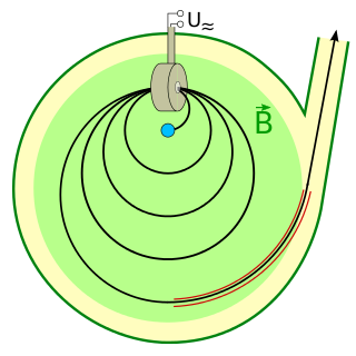
A cyclotron is a type of particle accelerator invented by Ernest Lawrence in 1929–1930 at the University of California, Berkeley, and patented in 1932. A cyclotron accelerates charged particles outwards from the center of a flat cylindrical vacuum chamber along a spiral path. The particles are held to a spiral trajectory by a static magnetic field and accelerated by a rapidly varying electric field. Lawrence was awarded the 1939 Nobel Prize in Physics for this invention.

<span class="mw-page-title-main">Fermilab</span> High-energy particle physics laboratory in Illinois, US

Fermi National Accelerator Laboratory (Fermilab), located in Batavia, Illinois, near Chicago, is a United States Department of Energy national laboratory specializing in high-energy particle physics.

<span class="mw-page-title-main">Tevatron</span> Defunct American particle accelerator at Fermilab in Illinois (1983–2011)

The Tevatron was a circular particle accelerator in the United States, at the Fermi National Accelerator Laboratory, east of Batavia, Illinois, and was the highest energy particle collider until the Large Hadron Collider (LHC) of the European Organization for Nuclear Research (CERN) was built near Geneva, Switzerland. The Tevatron was a synchrotron that accelerated protons and antiprotons in a 6.28 km (3.90 mi) circumference ring to energies of up to 1 TeV, hence its name. The Tevatron was completed in 1983 at a cost of $120 million and significant upgrade investments were made during its active years of 1983–2011.

<span class="mw-page-title-main">Klystron</span> Vacuum tube used for amplifying radio waves

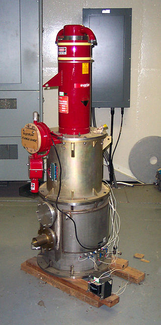
A klystron is a specialized linear-beam vacuum tube, invented in 1937 by American electrical engineers Russell and Sigurd Varian, which is used as an amplifier for high radio frequencies, from UHF up into the microwave range. Low-power klystrons are used as oscillators in terrestrial microwave relay communications links, while high-power klystrons are used as output tubes in UHF television transmitters, satellite communication, radar transmitters, and to generate the drive power for modern particle accelerators.

<span class="mw-page-title-main">Electron gun</span> Electrical component producing a narrow electron beam

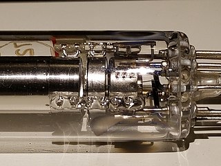
An electron gun is an electrical component in some vacuum tubes that produces a narrow, collimated electron beam that has a precise kinetic energy.

<span class="mw-page-title-main">Synchrocyclotron</span> Special type of cyclic particle accelerator

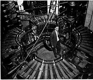
A synchrocyclotron is a special type of cyclotron, patented by Edwin McMillan in 1952, in which the frequency of the driving RF electric field is varied to compensate for relativistic effects as the particles' velocity begins to approach the speed of light. This is in contrast to the classical cyclotron, where this frequency is constant.

<span class="mw-page-title-main">Synchrotron</span> Type of cyclic particle accelerator

A synchrotron is a particular type of cyclic particle accelerator, descended from the cyclotron, in which the accelerating particle beam travels around a fixed closed-loop path. The magnetic field which bends the particle beam into its closed path increases with time during the accelerating process, being synchronized to the increasing kinetic energy of the particles. The synchrotron is one of the first accelerator concepts to enable the construction of large-scale facilities, since bending, beam focusing and acceleration can be separated into different components. The most powerful modern particle accelerators use versions of the synchrotron design. The largest synchrotron-type accelerator, also the largest particle accelerator in the world, is the 27-kilometre-circumference (17 mi) Large Hadron Collider (LHC) near Geneva, Switzerland, built in 2008 by the European Organization for Nuclear Research (CERN). It can accelerate beams of protons to an energy of 7 tera electronvolts (TeV or 1012 eV).

<span class="mw-page-title-main">KEK</span> Japanese high-energy physics organization

The High Energy Accelerator Research Organization, known as KEK, is a Japanese organization whose purpose is to operate the largest particle physics laboratory in Japan, situated in Tsukuba, Ibaraki prefecture. It was established in 1997. The term "KEK" is also used to refer to the laboratory itself, which employs approximately 695 employees. KEK's main function is to provide the particle accelerators and other infrastructure needed for high-energy physics, material science, structural biology, radiation science, computing science, nuclear transmutation and so on. Numerous experiments have been constructed at KEK by the internal and international collaborations that have made use of them. Makoto Kobayashi, emeritus professor at KEK, is known globally for his work on CP-violation, and was awarded the 2008 Nobel Prize in Physics.

A particle beam is a stream of charged or neutral particles. In particle accelerators, these particles can move with a velocity close to the speed of light. There is a difference between the creation and control of charged particle beams and neutral particle beams, as only the first type can be manipulated to a sufficient extent by devices based on electromagnetism. The manipulation and diagnostics of charged particle beams at high kinetic energies using particle accelerators are main topics of accelerator physics.

Plasma acceleration is a technique for accelerating charged particles, such as electrons or ions, using the electric field associated with electron plasma wave or other high-gradient plasma structures. These plasma acceleration structures are created using either ultra-short laser pulses or energetic particle beams that are matched to the plasma parameters. The technique offers a way to build affordable and compact particle accelerators.

<span class="mw-page-title-main">AWAKE</span>

The AWAKE facility at CERN is a proof-of-principle experiment, which investigates wakefield plasma acceleration using a proton bunch as a driver, a world-wide first. It aims to accelerate a low-energy witness bunch of electrons from 15 to 20 MeV to several GeV over a short distance by creating a high acceleration gradient of several GV/m. Particle accelerators currently in use, like CERN's LHC, use standard or superconductive RF-cavities for acceleration, but they are limited to an acceleration gradient in the order of 100 MV/m.

<span class="mw-page-title-main">Proton Synchrotron</span> CERNs first synchrotron accelerator

The Proton Synchrotron is a particle accelerator at CERN. It is CERN's first synchrotron, beginning its operation in 1959. For a brief period the PS was the world's highest energy particle accelerator. It has since served as a pre-accelerator for the Intersecting Storage Rings (ISR) and the Super Proton Synchrotron (SPS), and is currently part of the Large Hadron Collider (LHC) accelerator complex. In addition to protons, PS has accelerated alpha particles, oxygen and sulfur nuclei, electrons, positrons, and antiprotons.

<span class="mw-page-title-main">Microtron</span>

A microtron is a type of particle accelerator concept originating from the cyclotron in which the accelerating field is not applied through large D-shaped electrodes, but through a linear accelerator structure. The classic microtron was invented by Vladimir Veksler around 1944. The kinetic energy of the particles is increased by a constant amount per field change. Microtrons are designed to operate at constant field frequency and magnetic field in the ultrarelativistic limit. Thus they are especially suited for very light elementary particles, namely electrons.

<span class="mw-page-title-main">Particle accelerator</span> Research apparatus for particle physics

A particle accelerator is a machine that uses electromagnetic fields to propel charged particles to very high speeds and energies, and to contain them in well-defined beams.

<span class="mw-page-title-main">Vladimir Teplyakov</span>

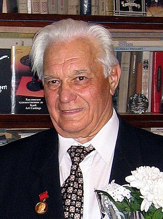
Vladimir Aleksandrovich Teplyakov was a Russian experimental physicist known for his work on particle accelerators. Together with I.M. Kapchinsky, he invented the principle of the radio-frequency quadrupole (RFQ), which revolutionized the acceleration of low-energy charged particle beams.

<span class="mw-page-title-main">Radio-frequency quadrupole</span>

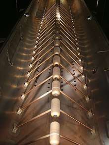
A radio-frequency quadrupole (RFQ) is a linear accelerator component generally used at low beam energies, roughly 2keV to 3MeV. It is similar in layout to a quadrupole mass analyser but its purpose is to accelerate a single-species beam rather than perform mass spectrometry on a multiple-species beam. As charged particles are accelerated along the beam line they alternately experience electric fields in two axes at right angles to the direction of motion, offset in phase, such that there is always a forwards force in the beam direction (Z), plus a beam focussing action alternately in X and then in Y. This is achieved by exciting 4 electrodes that run the length of the accelerator, and are shaped to have a periodically varying gap that matches the RF frequency to the beam velocity at that point in the accelerator. This causes the particles to form bunches in step with the exciting frequency, such that they pass through each region as the local field is near the acceleration maxima. There are two common electrode shapes, either a group of 4 vanes with a wave pattern on the tips that approach, or 4 cylinders with periodic conical sections. The electrodes are mounted in vacuum and excited from by suitably phased signals from a high power RF source. The advantages over a conventional RF LINAC with separated RF cavities and drift tubes are firstly that the beam is constantly accelerating so the design can be made considerably more compact for a given energy, and secondly the bunching and focussing of the beam.

<span class="mw-page-title-main">CERN Hadron Linacs</span> Group of particle accelerators

The CERN Hadron Linacs are linear accelerators that accelerate beams of hadrons from a standstill to be used by the larger circular accelerators at the facility.

An energy recovery linac (ERL) is a type of linear particle accelerator that provides a beam of electrons used to produce x-rays by synchrotron radiation. First proposed in 1965 the idea gained interest since the early 2000s.

<span class="mw-page-title-main">LHeC</span> Accelerator study for a possible upgrade of the existing LHC storage ring

The Large Hadron Electron Collider (LHeC) is an accelerator study for a possible upgrade of the existing LHC storage ring - the currently highest energy proton accelerator operating at CERN in Geneva. By adding to the proton accelerator ring a new electron accelerator, the LHeC would enable the investigation of electron-proton and electron-ion collisions at unprecedented high energies and rate, much higher than had been possible at the electron-proton collider HERA at DESY at Hamburg, which terminated its operation in 2007. The LHeC has therefore a unique program of research, as on the substructure of the proton and nuclei or the physics of the newly discovered Higgs boson. It is an electron–ion collider, similar to the plans in the US and elsewhere, although the present design would not include polarized protons.

<span class="mw-page-title-main">LEP Pre-Injector</span>

The LEP Pre-Injector (LPI) was the initial source that provided electrons and positrons to CERN's accelerator complex for the Large Electron–Positron Collider (LEP) from 1989 until 2000.

References

  1. G. Ising (1924). "Prinzip einer Methode zur Herstellung von Kanalstrahlen hoher Voltzahl". Arkiv för Matematik, Astronomi och Fysik. 18 (30): 1–4.
  2. Widerøe, R. (17 December 1928). "Über Ein Neues Prinzip Zur Herstellung Hoher Spannungen". Archiv für Elektronik und Übertragungstechnik. 21 (4): 387–406. doi:10.1007/BF01656341. S2CID   109942448.
  3. Bryant, P J (1994). A brief history and review of accelerators. 5th General Accelerator Physics Course. CERN Accelerator School. doi:10.5170/CERN-1994-001.1.
  4. Mangan, Michelangelo (2016). "Particle accelerators and the progress of particle physics". In Brüning, Oliver; Myers, Stephen (eds.). Challenges and goals for accelerators in the XXI century. Hackensack, New Jersey: World Scientific. p. 33. Bibcode:2016cgat.book.....M. doi:10.1142/8635. ISBN   978-981-4436-39-7.
  5. Heilbron, J.L.; Seidel, Robert W. (1989). Lawrence and His Laboratory: A History of the Lawrence Berkeley Laboratory, Volume I. Berkeley, CA: University of California Press. Retrieved 2 February 2022.
  6. Conte, Mario; MacKay, William (2008). An introduction to the physics of particle accelerators (2nd ed.). Hackensack, N.J.: World Scientific. ISBN   9789812779601.
  7. "Alvarez proton linear accelerator". Smithsonian Institution. Retrieved 3 February 2022.
  8. Lapostolle, Pierre (July 1989). Proton Linear Accelerators: A Theoretical and Historical Introduction (Report). Los Alamos National Laboratory. LA-11601-MS. Retrieved February 4, 2022.
  9. Ginzton, Edward L. (April 1983). "Early Accelerator Work at Stanford" (PDF). SLAC Beam Line: 2–16.
  10. Neal, R. B. (1968). "Chap. 5" (PDF). The Stanford Two-Mile Accelerator. New York, New York: W.A. Benjamin, Inc. p. 59. Retrieved 2010-09-17.
  11. Stokes, Richard H.; Wangler, Thomas P. (1988). "Radiofrequency Quadrupole Accelerators and their Applications". Annual Review of Nuclear and Particle Science. 38 (38): 97–118. Bibcode:1988ARNPS..38...97S. doi: 10.1146/annurev.ns.38.120188.000525 . Retrieved 3 February 2022.
  12. Reiser, Martin (2008). Theory and design of charged particle beams (2nd ed.). Weinheim: Wiley-VCH. p. 6. ISBN   9783527407415.
  13. Padamsee, Hasan (April 14, 2020). "History of gradient advances in SRF". arXiv: 2004.06720 [physics.acc-ph].
  14. Westfall, Catherine (April 1997). The Prehistory of Jefferson Lab's SRF Accelerating Cavities, 1962 to 1985 (Report). Thomas Jefferson National Accelerator Facility. JLAB-PHY-97-35.
  15. Ostroumov, Peter; Gerigk, Frank (January 2013). "Superconducting Hadron Linacs". Reviews of Accelerator Science and Technology. 06: 171–196. doi:10.1142/S1793626813300089.
  16. 1 2 3 Conte, Mario; MacKay, William (2008). An introduction to the physics of particle accelerators (2nd ed.). Hackensack, N.J.: World Scientific. p. 1. ISBN   9789812779601.
  17. 1 2 Edwards, D. A.; Syphers, M.J. (1993). An introduction to the physics of high energy accelerators. New York: Wiley. ISBN   9780471551638.
  18. Podgorsak, E B (2005). "Treatment Machines for External Beam Radiotherapy". Radiation Oncology Physics. Vienna: International Atomic Energy Agency. p. 138. ISBN   92-0-107304-6.
  19. Blewett, J P (11 June 1956). Edouard Regenstreif (ed.). Linear Accelerator Injectors for Proton Synchrotrons. CERN Symposium on High Energy Accelerators and Pion Physics. Vol. 1. Geneva: CERN. pp. 159–166. doi:10.5170/CERN-1956-025.
  20. Weise, Hans; Decking, Winfried (10 July 2017). "The world's longest superconducting linac". CERN Courier . IOP Publishing.
  21. Faircloth, D C (24 March 2021). "Particle Sources". arXiv: 2103.13231 [physics.acc-ph].
  22. "Heavy ions offer a new approach to fusion". CERN Courier. 2002-06-25. Retrieved 2021-01-22.
  23. Christofilos, N. C.; Hester, R. E.; Lamb, W. a. S.; Reagan, D. D.; Sherwood, W. A.; Wright, R. E. (1964-07-01). "High Current Linear Induction Accelerator for Electrons". Review of Scientific Instruments. 35 (7): 886–890. Bibcode:1964RScI...35..886C. doi:10.1063/1.1746846. ISSN   0034-6748.
  24. Fraas, H. (1989). "Kern- und Elementarteilchenphysik. Von G. Musiol, J. Ranft, R. Reif und D. Seeliger, VCH Verlagsgesellschaft Weinheim, 1988, DM 128". Physik in unserer Zeit. 20 (1): 31. Bibcode:1989PhuZ...20...31F. doi:10.1002/piuz.19890200109. ISSN   0031-9252.
  25. Jaeschke, Eberhard; Khan, Shaukat; Schneider, Jochen R.; Hastings, Jerome B., eds. (2016). Synchrotron Light Sources and Free-Electron Lasers: Accelerator Physics, Instrumentation and Science Applications. Springer International Publishing. ISBN   978-3-319-14393-4.
  26. Raubenheimer, T. O. (2000). A 3 TeV e+e− linear collider based on CLIC technology. Geneva. ISBN   92-9083-168-5.{{cite book}}: CS1 maint: location missing publisher (link)
  27. "LIGHT: A LINEAR ACCELERATOR FOR PROTON THERAPY" (PDF).
  28. Ginzton, E. L.; Hansen, W. W.; Kennedy, W. R. (1948-02-01). "A Linear Electron Accelerator". Review of Scientific Instruments. 19 (2): 89–108. Bibcode:1948RScI...19...89G. doi:10.1063/1.1741225. ISSN   0034-6748. PMID   18908606.
  29. Thwaites, DI and Tuohy J (2006). "Back to the future: the history and development of the clinical linear accelerator". Phys. Med. Biol. 51 (13): R343–R36. doi:10.1088/0031-9155/51/13/R20. PMID   16790912. S2CID   7672187.
  30. Gahl and Flagg (2009).Solution Target Radioisotope Generator Technical Review. Subcritical Fission Mo99 Production. Retrieved 6 January 2013.