Mechanical advantage is a measure of the force amplification achieved by using a tool, mechanical device or machine system. The device trades off input forces against movement to obtain a desired amplification in the output force. The model for this is the law of the lever. Machine components designed to manage forces and movement in this way are called mechanisms.[1] An ideal mechanism transmits power without adding to or subtracting from it. This means the ideal machine does not include a power source, is frictionless, and is constructed from rigid bodies that do not deflect or wear. The performance of a real system relative to this ideal is expressed in terms of efficiency factors that take into account departures from the ideal.
The lever is a movable bar that pivots on a fulcrum attached to or positioned on or across a fixed point. The lever operates by applying forces at different distances from the fulcrum, or pivot. The location of the fulcrum determines a lever's class. Where a lever rotates continuously, it functions as a rotary 2nd-class lever. The motion of the lever's end-point describes a fixed orbit, where mechanical energy can be exchanged. (see a hand-crank as an example.)
In modern times, this kind of rotary leverage is widely used; see a (rotary) 2nd-class lever; see gears, pulleys or friction drive, used in a mechanical power transmission scheme. It is common for mechanical advantage to be manipulated in a 'collapsed' form, via the use of more than one gear (a gearset). In such a gearset, gears having smaller radii and less inherent mechanical advantage are used. In order to make use of non-collapsed mechanical advantage, it is necessary to use a 'true length' rotary lever. See, also, the incorporation of mechanical advantage into the design of certain types of electric motors; one design is an 'outrunner'.
As the lever pivots on the fulcrum, points farther from this pivot move faster than points closer to the pivot. The power into and out of the lever is the same, so must come out the same when calculations are being done. Power is the product of force and velocity, so forces applied to points farther from the pivot must be less than when applied to points closer in.[1]
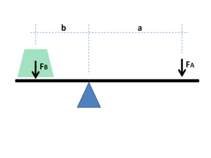
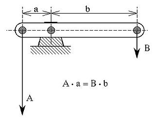
If a and b are distances from the fulcrum to points A and B and if force FA applied to A is the input force and FB exerted at B is the output, the ratio of the velocities of points A and B is given by a/b so the ratio of the output force to the input force, or mechanical advantage, is given by
This is the law of the lever, which Archimedes formulated using geometric reasoning.[2] It shows that if the distance a from the fulcrum to where the input force is applied (point A) is greater than the distance b from fulcrum to where the output force is applied (point B), then the lever amplifies the input force. If the distance from the fulcrum to the input force is less than from the fulcrum to the output force, then the lever reduces the input force. To Archimedes, who recognized the profound implications and practicalities of the law of the lever, has been attributed the famous claim, "Give me a place to stand and with a lever I will move the whole world."[3]
The use of velocity in the static analysis of a lever is an application of the principle of virtual work.
The requirement for power input to an ideal mechanism to equal power output provides a simple way to compute mechanical advantage from the input-output speed ratio of the system.
The power input to a gear train with a torque TA applied to the drive pulley which rotates at an angular velocity of ωA is P=TAωA.
Because the power flow is constant, the torque TB and angular velocity ωB of the output gear must satisfy the relation
which yields
This shows that for an ideal mechanism the input-output speed ratio equals the mechanical advantage of the system. This applies to all mechanical systems ranging from robots to linkages.
Gear teeth are designed so that the number of teeth on a gear is proportional to the radius of its pitch circle, and so that the pitch circles of meshing gears roll on each other without slipping. The speed ratio for a pair of meshing gears can be computed from ratio of the radii of the pitch circles and the ratio of the number of teeth on each gear, its gear ratio.
Two meshing gears transmit rotational motion.
The velocity v of the point of contact on the pitch circles is the same on both gears, and is given by
where input gear A has radius rA and meshes with output gear B of radius rB, therefore,
where NA is the number of teeth on the input gear and NB is the number of teeth on the output gear.
The mechanical advantage of a pair of meshing gears for which the input gear has NA teeth and the output gear has NB teeth is given by
This shows that if the output gear GB has more teeth than the input gear GA, then the gear train amplifies the input torque. And, if the output gear has fewer teeth than the input gear, then the gear train reduces the input torque.
If the output gear of a gear train rotates more slowly than the input gear, then the gear train is called a speed reducer (Force multiplier). In this case, because the output gear must have more teeth than the input gear, the speed reducer will amplify the input torque.
Chain and belt drives
Mechanisms consisting of two sprockets connected by a chain, or two pulleys connected by a belt are designed to provide a specific mechanical advantage in power transmission systems.
The velocity v of the chain or belt is the same when in contact with the two sprockets or pulleys:
where the input sprocket or pulley A meshes with the chain or belt along the pitch radius rA and the output sprocket or pulley B meshes with this chain or belt along the pitch radius rB,
therefore
where NA is the number of teeth on the input sprocket and NB is the number of teeth on the output sprocket. For a toothed belt drive, the number of teeth on the sprocket can be used. For friction belt drives the pitch radius of the input and output pulleys must be used.
The mechanical advantage of a pair of a chain drive or toothed belt drive with an input sprocket with NA teeth and the output sprocket has NB teeth is given by
The mechanical advantage for friction belt drives is given by
Chains and belts dissipate power through friction, stretch and wear, which means the power output is actually less than the power input, which means the mechanical advantage of the real system will be less than that calculated for an ideal mechanism. A chain or belt drive can lose as much as 5% of the power through the system in friction heat, deformation and wear, in which case the efficiency of the drive is 95%.
Example: bicycle chain drive
Mechanical advantage in different gears of a bicycle. Typical forces applied to the bicycle pedal and to the ground are shown, as are corresponding distances moved by the pedal and rotated by the wheel. Note that even in low gear the MA of a bicycle is less than 1.
Consider the 18-speed bicycle with 7in (radius) cranks and 26in (diameter) wheels. If the sprockets at the crank and at the rear drive wheel are the same size, then the ratio of the output force on the tire to the input force on the pedal can be calculated from the law of the lever to be
Now, assume that the front sprockets have a choice of 28 and 52 teeth, and that the rear sprockets have a choice of 16 and 32 teeth. Using different combinations, we can compute the following speed ratios between the front and rear sprockets
Speed ratios and total MA
input (small)
input (large)
output (small)
output (large)
speed ratio
crank-wheel ratio
total MA
low speed
28
-
-
32
1.14
0.54
0.62
mid 1
-
52
-
32
0.62
0.54
0.33
mid 2
28
-
16
-
0.57
0.54
0.31
high speed
-
52
16
-
0.30
0.54
0.16
The ratio of the force driving the bicycle to the force on the pedal, which is the total mechanical advantage of the bicycle, is the product of the speed ratio (or teeth ratio of output sprocket/input sprocket) and the crank-wheel lever ratio.
Notice that in every case the force on the pedals is greater than the force driving the bicycle forward (in the illustration above, the corresponding backward-directed reaction force on the ground is indicated).
Block and tackle
A block and tackle is an assembly of a rope and pulleys that is used to lift loads. A number of pulleys are assembled together to form the blocks, one that is fixed and one that moves with the load. The rope is threaded through the pulleys to provide mechanical advantage that amplifies that force applied to the rope.[4]
In order to determine the mechanical advantage of a block and tackle system consider the simple case of a gun tackle, which has a single mounted, or fixed, pulley and a single movable pulley. The rope is threaded around the fixed block and falls down to the moving block where it is threaded around the pulley and brought back up to be knotted to the fixed block.
The mechanical advantage of a block and tackle equals the number of sections of rope that support the moving block; shown here it is 2, 3, 4, 5, and 6, respectively.
Let S be the distance from the axle of the fixed block to the end of the rope, which is A where the input force is applied. Let R be the distance from the axle of the fixed block to the axle of the moving block, which is B where the load is applied.
The total length of the rope L can be written as
where K is the constant length of rope that passes over the pulleys and does not change as the block and tackle moves.
The velocities VA and VB of the points A and B are related by the constant length of the rope, that is
or
The negative sign shows that the velocity of the load is opposite to the velocity of the applied force, which means as we pull down on the rope the load moves up.
Let VA be positive downwards and VB be positive upwards, so this relationship can be written as the speed ratio
where 2 is the number of rope sections supporting the moving block.
Let FA be the input force applied at A the end of the rope, and let FB be the force at B on the moving block. Like the velocities FA is directed downwards and FB is directed upwards.
For an ideal block and tackle system there is no friction in the pulleys and no deflection or wear in the rope, which means the power input by the applied force FAVA must equal the power out acting on the load FBVB, that is
The ratio of the output force to the input force is the mechanical advantage of an ideal gun tackle system,
This analysis generalizes to an ideal block and tackle with a moving block supported by n rope sections,
This shows that the force exerted by an ideal block and tackle is n times the input force, where n is the number of sections of rope that support the moving block.
Efficiency
Mechanical advantage that is computed using the assumption that no power is lost through deflection, friction and wear of a machine is the maximum performance that can be achieved. For this reason, it is often called the ideal mechanical advantage (IMA). In operation, deflection, friction and wear will reduce the mechanical advantage. The amount of this reduction from the ideal to the actual mechanical advantage (AMA) is defined by a factor called efficiency, a quantity which is determined by experimentation.
As an example, using a block and tackle with six rope sections and a 600lb load, the operator of an ideal system would be required to pull the rope six feet and exert 100lbF of force to lift the load one foot. Both the ratios Fout / Fin and Vin / Vout show that the IMA is six. For the first ratio, 100lbF of force input results in 600lbF of force out. In an actual system, the force out would be less than 600 pounds due to friction in the pulleys. The second ratio also yields a MA of 6 in the ideal case but a smaller value in the practical scenario; it does not properly account for energy losses such as rope stretch. Subtracting those losses from the IMA or using the first ratio yields the AMA.
Ideal mechanical advantage
The ideal mechanical advantage (IMA), or theoretical mechanical advantage, is the mechanical advantage of a device with the assumption that its components do not flex, there is no friction, and there is no wear. It is calculated using the physical dimensions of the device and defines the maximum performance the device can achieve.
The assumptions of an ideal machine are equivalent to the requirement that the machine does not store or dissipate energy; the power into the machine thus equals the power out. Therefore, the power P is constant through the machine and force times velocity into the machine equals the force times velocity out—that is,
The ideal mechanical advantage is the ratio of the force out of the machine (load) to the force into the machine (effort), or
Applying the constant power relationship yields a formula for this ideal mechanical advantage in terms of the speed ratio:
The speed ratio of a machine can be calculated from its physical dimensions. The assumption of constant power thus allows use of the speed ratio to determine the maximum value for the mechanical advantage.
Actual mechanical advantage
The actual mechanical advantage (AMA) is the mechanical advantage determined by physical measurement of the input and output forces. Actual mechanical advantage takes into account energy loss due to deflection, friction, and wear.
The AMA of a machine is calculated as the ratio of the measured force output to the measured force input,
where the input and output forces are determined experimentally.
The ratio of the experimentally determined mechanical advantage to the ideal mechanical advantage is the mechanical efficiency η of the machine,
In classical mechanics, a harmonic oscillator is a system that, when displaced from its equilibrium position, experiences a restoring force F proportional to the displacement x:
A pulley is a wheel on an axle or shaft enabling a taut cable or belt passing over the wheel to move and change direction, or transfer power between itself and a shaft. A sheave or pulley wheel is a pulley using an axle supported by a frame or shell (block) to guide a cable or exert force.
In physics, power is the amount of energy transferred or converted per unit time. In the International System of Units, the unit of power is the watt, equal to one joule per second. In older works, power is sometimes called activity. Power is a scalar quantity.
A simple machine is a mechanical device that changes the direction or magnitude of a force. In general, they can be defined as the simplest mechanisms that use mechanical advantage to multiply force. Usually the term refers to the six classical simple machines that were defined by Renaissance scientists:
In physics and mechanics, torque is the rotational analogue of linear force. It is also referred to as the moment of force. The symbol for torque is typically , the lowercase Greek letter tau. When being referred to as moment of force, it is commonly denoted by M. Just as a linear force is a push or a pull applied to a body, a torque can be thought of as a twist applied to an object with respect to a chosen point; for example, driving a screw uses torque, which is applied by the screwdriver rotating around its axis. A force of three newtons applied two metres from the fulcrum, for example, exerts the same torque as a force of one newton applied six metres from the fulcrum.
A lever is a simple machine consisting of a beam or rigid rod pivoted at a fixed hinge, or fulcrum. A lever is a rigid body capable of rotating on a point on itself. On the basis of the locations of fulcrum, load and effort, the lever is divided into three types. It is one of the six simple machines identified by Renaissance scientists. A lever amplifies an input force to provide a greater output force, which is said to provide leverage, which is mechanical advantage gained in the system, equal to the ratio of the output force to the input force. As such, the lever is a mechanical advantage device, trading off force against movement.
A machine is a physical system that uses power to apply forces and control movement to perform an action. The term is commonly applied to artificial devices, such as those employing engines or motors, but also to natural biological macromolecules, such as molecular machines. Machines can be driven by animals and people, by natural forces such as wind and water, and by chemical, thermal, or electrical power, and include a system of mechanisms that shape the actuator input to achieve a specific application of output forces and movement. They can also include computers and sensors that monitor performance and plan movement, often called mechanical systems.
A block and tackle or only tackle is a system of two or more pulleys with a rope or cable threaded between them, usually used to lift heavy loads.
An epicyclic gear train is a gear reduction assembly consisting of two gears mounted so that the center of one gear revolves around the center of the other. A carrier connects the centers of the two gears and rotates, to carry the planet gear(s) around the sun gear. The planet and sun gears mesh so that their pitch circles roll without slip. If the sun gear is held fixed, then a point on the pitch circle of the planet gear traces an epicycloid curve.
In mechanics, virtual work arises in the application of the principle of least action to the study of forces and movement of a mechanical system. The work of a force acting on a particle as it moves along a displacement is different for different displacements. Among all the possible displacements that a particle may follow, called virtual displacements, one will minimize the action. This displacement is therefore the displacement followed by the particle according to the principle of least action.
The work of a force on a particle along a virtual displacement is known as the virtual work.
The wheel and axle is a simple machine consisting of a wheel attached to a smaller axle so that these two parts rotate together in which a force is transferred from one to the other. The wheel and axle can be viewed as a version of the lever, with a drive force applied tangentially to the perimeter of the wheel, and a load force applied to the axle supported in a bearing, which serves as a fulcrum.
A gear train or gear set is a machine element of a mechanical system formed by mounting two or more gears on a frame such that the teeth of the gears engage.
A mechanical amplifier or a mechanical amplifying element is a linkage mechanism that amplifies the magnitude of mechanical quantities such as force, displacement, velocity, acceleration and torque in linear and rotational systems. In some applications, mechanical amplification induced by nature or unintentional oversights in man-made designs can be disastrous, causing situations such as the 1940 Tacoma Narrows Bridge collapse. When employed appropriately, it can help to magnify small mechanical signals for practical applications.
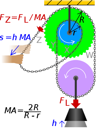
A differential pulley —also called "Weston differential pulley", sometimes "differential hoist", "chain hoist", or colloquially "chain fall"— is used to manually lift very heavy objects like car engines. It is operated by pulling upon the slack section of a continuous chain that wraps around two pulleys on a common shaft. The relative sizing of the two connected pulleys determines the maximum weight that can be lifted by hand. If the pulley radii are close enough, then the load will remain in place until the chain is pulled.
The theory of sonics is a branch of continuum mechanics which describes the transmission of mechanical energy through vibrations. The birth of the theory of sonics is the publication of the book A treatise on transmission of power by vibrations in 1918 by the Romanian scientist Gogu Constantinescu.
ONE of the fundamental problems of mechanical engineering is that of transmitting energy found in nature, after suitable transformation, to some point at which can be made available for performing useful work. The methods of transmitting power known and practised by engineers are broadly included in two classes: mechanical including hydraulic, pneumatic and wire rope methods; and electrical methods....According to the new system, energy is transmitted from one point to another, which may be at a considerable distance, by means of impressed variations of pressure or tension producing longitudinal vibrations in solid, liquid or gaseous columns. The energy is transmitted by periodic changes of pressure and volume in the longitudinal direction and may be described as wave transmission of power, or mechanical wave transmission. – Gogu Constantinescu
Strain wave gearing is a type of mechanical gear system that uses a flexible spline with external teeth, which is deformed by a rotating elliptical plug to engage with the internal gear teeth of an outer spline.
The impedance analogy is a method of representing a mechanical system by an analogous electrical system. The advantage of doing this is that there is a large body of theory and analysis techniques concerning complex electrical systems, especially in the field of filters. By converting to an electrical representation, these tools in the electrical domain can be directly applied to a mechanical system without modification. A further advantage occurs in electromechanical systems: Converting the mechanical part of such a system into the electrical domain allows the entire system to be analysed as a unified whole.
A simple machine that exhibits mechanical advantage is called a mechanical advantage device - e.g.:
The mobility analogy, also called admittance analogy or Firestone analogy, is a method of representing a mechanical system by an analogous electrical system. The advantage of doing this is that there is a large body of theory and analysis techniques concerning complex electrical systems, especially in the field of filters. By converting to an electrical representation, these tools in the electrical domain can be directly applied to a mechanical system without modification. A further advantage occurs in electromechanical systems: Converting the mechanical part of such a system into the electrical domain allows the entire system to be analysed as a unified whole.
In control system theory, and various branches of engineering, a transfer function matrix, or just transfer matrix is a generalisation of the transfer functions of single-input single-output (SISO) systems to multiple-input and multiple-output (MIMO) systems. The matrix relates the outputs of the system to its inputs. It is a particularly useful construction for linear time-invariant (LTI) systems because it can be expressed in terms of the s-plane.
References
1 2 Uicker, John J.; Pennock, G. R.; Shigley, J. E. (2011). Theory of machines and mechanisms. New York: Oxford University Press. ISBN978-0-19-537123-9.
This page is based on this Wikipedia article Text is available under the CC BY-SA 4.0 license; additional terms may apply. Images, videos and audio are available under their respective licenses.