A mechanical linkage is an assembly of systems connected to manage forces and movement. The movement of a body, or link, is studied using geometry so the link is considered to be rigid.[1] The connections between links are modeled as providing ideal movement, pure rotation or sliding for example, and are called joints. A linkage modeled as a network of rigid links and ideal joints is called a kinematic chain.
Linkages may be constructed from open chains, closed chains, or a combination of open and closed chains. Each link in a chain is connected by a joint to one or more other links. Thus, a kinematic chain can be modeled as a graph in which the links are paths and the joints are vertices, which is called a linkage graph.
The deployable mirror linkage is constructed from a series of rhombus or scissor linkages.An extended scissor lift
The movement of an ideal joint is generally associated with a subgroup of the group of Euclidean displacements. The number of parameters in the subgroup is called the degrees of freedom (DOF) of the joint. Mechanical linkages are usually designed to transform a given input force and movement into a desired output force and movement. The ratio of the output force to the input force is known as the mechanical advantage of the linkage, while the ratio of the input speed to the output speed is known as the speed ratio. The speed ratio and mechanical advantage are defined so they yield the same number in an ideal linkage.
A kinematic chain, in which one link is fixed or stationary, is called a mechanism,[2] and a linkage designed to be stationary is called a structure.
History
Archimedes[3] applied geometry to the study of the lever. Into the 1500s the work of Archimedes and Hero of Alexandria were the primary sources of machine theory. It was Leonardo da Vinci who brought an inventive energy to machines and mechanism.[4]
In the mid-1700s the steam engine was of growing importance, and James Watt realized that efficiency could be increased by using different cylinders for expansion and condensation of the steam. This drove his search for a linkage that could transform rotation of a crank into a linear slide, and resulted in his discovery of what is called Watt's linkage. This led to the study of linkages that could generate straight lines, even if only approximately; and inspired the mathematician J. J. Sylvester, who lectured on the Peaucellier linkage, which generates an exact straight line from a rotating crank.[5]
The work of Sylvester inspired A. B. Kempe, who showed that linkages for addition and multiplication could be assembled into a system that traced a given algebraic curve.[6] Kempe's design procedure has inspired research at the intersection of geometry and computer science.[7][8]
In the late 1800s F. Reuleaux, A. B. W. Kennedy, and L. Burmester formalized the analysis and synthesis of linkage systems using descriptive geometry, and P. L. Chebyshev introduced analytical techniques for the study and invention of linkages.[5]
In the mid-1900s F. Freudenstein and G. N. Sandor[9] used the newly developed digital computer to solve the loop equations of a linkage and determine its dimensions for a desired function, initiating the computer-aided design of linkages. Within two decades these computer techniques were integral to the analysis of complex machine systems[10][11] and the control of robot manipulators.[12]
R. E. Kaufman[13][14] combined the computer's ability to rapidly compute the roots of polynomial equations with a graphical user interface to unite Freudenstein's techniques with the geometrical methods of Reuleaux and Burmester and form KINSYN, an interactive computer graphics system for linkage design
The modern study of linkages includes the analysis and design of articulated systems that appear in robots, machine tools, and cable driven and tensegrity systems. These techniques are also being applied to biological systems and even the study of proteins.
Mobility
Simple linkages are capable of producing complicated motion.
The configuration of a system of rigid links connected by ideal joints is defined by a set of configuration parameters, such as the angles around a revolute joint and the slides along prismatic joints measured between adjacent links. The geometric constraints of the linkage allow calculation of all of the configuration parameters in terms of a minimum set, which are the input parameters. The number of input parameters is called the mobility, or degree of freedom, of the linkage system.
A system of n rigid bodies moving in space has 6n degrees of freedom measured relative to a fixed frame. Include this frame in the count of bodies, so that mobility is independent of the choice of the fixed frame, then we have M=6(N−1), where N=n+1 is the number of moving bodies plus the fixed body.
Joints that connect bodies in this system remove degrees of freedom and reduce mobility. Specifically, hinges and sliders each impose five constraints and therefore remove five degrees of freedom. It is convenient to define the number of constraints c that a joint imposes in terms of the joint's freedom f, where c=6−f. In the case of a hinge or slider, which are one degree of freedom joints, we have f=1 and therefore c=6−1=5.
Thus, the mobility of a linkage system formed from n moving links and j joints each with fi, i=1, ..., j, degrees of freedom can be computed as,
There are two important special cases: (i) a simple open chain, and (ii) a simple closed chain. A simple open chain consists of n moving links connected end to end by j joints, with one end connected to a ground link. Thus, in this case N=j+1 and the mobility of the chain is
For a simple closed chain, n moving links are connected end-to-end by n+1 joints such that the two ends are connected to the ground link forming a loop. In this case, we have N=j and the mobility of the chain is
An example of a simple open chain is a serial robot manipulator. These robotic systems are constructed from a series of links connected by six one degree-of-freedom revolute or prismatic joints, so the system has six degrees of freedom.
An example of a simple closed chain is the RSSR (revolute-spherical-spherical-revolute) spatial four-bar linkage. The sum of the freedom of these joints is eight, so the mobility of the linkage is two, where one of the degrees of freedom is the rotation of the coupler around the line joining the two S joints.
Planar and spherical movement
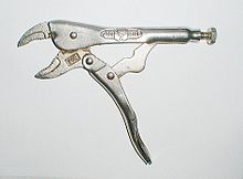
Linkage mobilityLocking pliers exemplify a four-bar, one degree of freedom mechanical linkage. The adjustable base pivot makes this a two degree-of-freedom five-bar linkage.
It is common practice to design the linkage system so that the movement of all of the bodies are constrained to lie on parallel planes, to form what is known as a planar linkage. It is also possible to construct the linkage system so that all of the bodies move on concentric spheres, forming a spherical linkage. In both cases, the degrees of freedom of the link is now three rather than six, and the constraints imposed by joints are now c=3−f.
In this case, the mobility formula is given by
and we have the special cases,
planar or spherical simple open chain,
planar or spherical simple closed chain,
An example of a planar simple closed chain is the planar four-bar linkage, which is a four-bar loop with four one degree-of-freedom joints and therefore has mobilityM=1.
Joints
The most familiar joints for linkage systems are the revolute, or hinged, joint denoted by an R, and the prismatic, or sliding, joint denoted by a P. Most other joints used for spatial linkages are modeled as combinations of revolute and prismatic joints. For example,
the cylindric joint consists of an RP or PR serial chain constructed so that the axes of the revolute and prismatic joints are parallel,
the universal joint consists of an RR serial chain constructed such that the axes of the revolute joints intersect at a 90° angle;
the spherical joint consists of an RRR serial chain for which each of the hinged joint axes intersect in the same point;
the planar joint can be constructed either as a planar RRR, RPR, and PPR serial chain that has three degrees-of-freedom.
Analysis and synthesis of linkages
The primary mathematical tool for the analysis of a linkage is known as the kinematics equations of the system. This is a sequence of rigid body transformation along a serial chain within the linkage that locates a floating link relative to the ground frame. Each serial chain within the linkage that connects this floating link to ground provides a set of equations that must be satisfied by the configuration parameters of the system. The result is a set of non-linear equations that define the configuration parameters of the system for a set of values for the input parameters.
Freudenstein introduced a method to use these equations for the design of a planar four-bar linkage to achieve a specified relation between the input parameters and the configuration of the linkage. Another approach to planar four-bar linkage design was introduced by L. Burmester, and is called Burmester theory.
Planar one degree-of-freedom linkages
The mobility formula provides a way to determine the number of links and joints in a planar linkage that yields a one degree-of-freedom linkage. If we require the mobility of a planar linkage to be M=1 and fi=1, the result is
or
This formula shows that the linkage must have an even number of links, so we have
N = 2, j = 1: this is a two-bar linkage known as the lever;
N = 6, j = 7: this is a six-bar linkage [ it has two links that have three joints, called ternary links, and there are two topologies of this linkage depending how these links are connected. In the Watt topology, the two ternary links are connected by a joint. In the Stephenson topology the two ternary links are connected by binary links;[15]
N = 8, j = 10: the eight-bar linkage has 16 different topologies;
N = 10, j = 13: the 10-bar linkage has 230 different topologies,
N = 12, j = 16: the 12-bar has 6856 topologies.
See Sunkari and Schmidt[16] for the number of 14- and 16-bar topologies, as well as the number of linkages that have two, three and four degrees-of-freedom.
The planar four-bar linkage is probably the simplest and most common linkage. It is a one degree-of-freedom system that transforms an input crank rotation or slider displacement into an output rotation or slide.
Examples of four-bar linkages are:
the crank-rocker, in which the input crank fully rotates and the output link rocks back and forth;
the slider-crank, in which the input crank rotates and the output slide moves back and forth;
drag-link mechanisms, in which the input crank fully rotates and drags the output crank in a fully rotational movement.
Types of four-bar linkages with link-lengths assigned to each link – observe the shortest link S and longest link L of each of these mechanism.
Other interesting linkages
Four-bar function generator approximating the function Log(u) for 1 < u < 10.
Five bar linkages often have meshing gears for two of the links, creating a one DOF linkage. They can provide greater power transmission with more design flexibility than four-bar linkages.
Toggle mechanisms are four-bar linkages that are dimensioned so that they can fold and lock. The toggle positions are determined by the colinearity of two of the moving links.[17] The linkage is dimensioned so that the linkage reaches a toggle position just before it folds. The high mechanical advantage allows the input crank to deform the linkage just enough to push it beyond the toggle position. This locks the input in place. Toggle mechanisms are used as clamps.
Peaucellier–Lipkin linkage, the first planar linkage to create a perfect straight line output from rotary input; eight-bar, one DOF.
A Scott Russell linkage, which converts linear motion, to (almost) linear motion in a line perpendicular to the input.
Chebyshev linkage, which provides nearly straight motion of a point with a four-bar linkage.
Hoekens linkage, which provides nearly straight motion of a point with a four-bar linkage.
Sarrus linkage, which provides motion of one surface in a direction normal to another.
Hart's inversor, which provides a perfect straight line motion without sliding guides.[18]
Biological linkages
Linkage systems are widely distributed in animals. The most thorough overview of the different types of linkages in animals has been provided by Mees Muller,[19] who also designed a new classification system which is especially well suited for biological systems. A well-known example is the cruciate ligaments of the knee.
An important difference between biological and engineering linkages is that revolving bars are rare in biology and that usually only a small range of the theoretically possible is possible due to additional functional constraints (especially the necessity to deliver blood).[20] Biological linkages frequently are compliant. Often one or more bars are formed by ligaments, and often the linkages are three-dimensional. Coupled linkage systems are known, as well as five-, six-, and even seven-bar linkages.[19]Four-bar linkages are by far the most common though.
Linkages can be found in joints, such as the knee of tetrapods, the hock of sheep, and the cranial mechanism of birds and reptiles. The latter is responsible for the upward motion of the upper bill in many birds.
Linkage mechanisms are especially frequent and manifold in the head of bony fishes, such as wrasses, which have evolved many specialized feeding mechanisms. Especially advanced are the linkage mechanisms of jaw protrusion. For suction feeding a system of linked four-bar linkages is responsible for the coordinated opening of the mouth and 3-D expansion of the buccal cavity. Other linkages are responsible for protrusion of the premaxilla.
Linkages are also present as locking mechanisms, such as in the knee of the horse, which enables the animal to sleep standing, without active muscle contraction. In pivot feeding, used by certain bony fishes, a four-bar linkage at first locks the head in a ventrally bent position by the alignment of two bars. The release of the locking mechanism jets the head up and moves the mouth toward the prey within 5–10 ms.
A simple machine is a mechanical device that changes the direction or magnitude of a force. In general, they can be defined as the simplest mechanisms that use mechanical advantage to multiply force. Usually the term refers to the six classical simple machines that were defined by Renaissance scientists:
A machine is a physical system using power to apply forces and control movement to perform an action. The term is commonly applied to artificial devices, such as those employing engines or motors, but also to natural biological macromolecules, such as molecular machines. Machines can be driven by animals and people, by natural forces such as wind and water, and by chemical, thermal, or electrical power, and include a system of mechanisms that shape the actuator input to achieve a specific application of output forces and movement. They can also include computers and sensors that monitor performance and plan movement, often called mechanical systems.
Kinematics is a subfield of physics, developed in classical mechanics, that describes the motion of points, bodies (objects), and systems of bodies without considering the forces that cause them to move. Kinematics, as a field of study, is often referred to as the "geometry of motion" and is occasionally seen as a branch of mathematics. A kinematics problem begins by describing the geometry of the system and declaring the initial conditions of any known values of position, velocity and/or acceleration of points within the system. Then, using arguments from geometry, the position, velocity and acceleration of any unknown parts of the system can be determined. The study of how forces act on bodies falls within kinetics, not kinematics. For further details, see analytical dynamics.
In the study of mechanisms, a four-bar linkage, also called a four-bar, is the simplest closed-chain movable linkage. It consists of four bodies, called bars or links, connected in a loop by four joints. Generally, the joints are configured so the links move in parallel planes, and the assembly is called a planar four-bar linkage. Spherical and spatial four-bar linkages also exist and are used in practice.
In physics, the degrees of freedom (DOF) of a mechanical system is the number of independent parameters that define its configuration or state. It is important in the analysis of systems of bodies in mechanical engineering, structural engineering, aerospace engineering, robotics, and other fields.
In mechanical engineering, an overconstrained mechanism is a linkage that has more degrees of freedom than is predicted by the mobility formula. The mobility formula evaluates the degree of freedom of a system of rigid bodies that results when constraints are imposed in the form of joints between the links.
Multibody system is the study of the dynamic behavior of interconnected rigid or flexible bodies, each of which may undergo large translational and rotational displacements.
In mechanical engineering, a kinematic diagram or kinematic scheme illustrates the connectivity of links and joints of a mechanism or machine rather than the dimensions or shape of the parts. Often links are presented as geometric objects, such as lines, triangles or squares, that support schematic versions of the joints of the mechanism or machine.
In classical mechanics, a kinematic pair is a connection between two physical objects that imposes constraints on their relative movement (kinematics). German engineer Franz Reuleaux introduced the kinematic pair as a new approach to the study of machines that provided an advance over the motion of elements consisting of simple machines.
In mechanical engineering, a kinematic chain is an assembly of rigid bodies connected by joints to provide constrained motion that is the mathematical model for a mechanical system. As the word chain suggests, the rigid bodies, or links, are constrained by their connections to other links. An example is the simple open chain formed by links connected in series, like the usual chain, which is the kinematic model for a typical robot manipulator.
The Sarrus linkage, invented in 1853 by Pierre Frédéric Sarrus, is a mechanical linkage to convert a limited circular motion to a linear motion or vice versa without reference guideways. It is a spatial six-bar linkage (6R) with two groups of three parallel adjacent joint-axes.
In kinematics, cognate linkages are linkages that ensure the same coupler curve geometry or input-output relationship, while being dimensionally dissimilar. In case of four-bar linkage coupler cognates, the Roberts–Chebyshev Theorem, after Samuel Roberts and Pafnuty Chebyshev, states that each coupler curve can be generated by three different four-bar linkages. These four-bar linkages can be constructed using similar triangles and parallelograms, and the Cayley diagram.
The Chebychev–Grübler–Kutzbach criterion determines the number of degrees of freedom of a kinematic chain, that is, a coupling of rigid bodies by means of mechanical constraints. These devices are also called linkages.
The Klannlinkage is a planar mechanism designed to simulate the gait of legged animal and function as a wheel replacement, a leg mechanism. The linkage consists of the frame, a crank, two grounded rockers, and two couplers all connected by pivot joints. It was developed by Joe Klann in 1994 as an expansion of Burmester curves which are used to develop four-bar double-rocker linkages such as harbor crane booms. It is categorized as a modified Stephenson type III kinematic chain.
In engineering, a mechanism is a device that transforms input forces and movement into a desired set of output forces and movement. Mechanisms generally consist of moving components which may include:
Jansen's linkage is a planar leg mechanism designed by the kinetic sculptor Theo Jansen to generate a smooth walking motion. Jansen has used his mechanism in a variety of kinetic sculptures which are known as Strandbeesten. Jansen's linkage bears artistic as well as mechanical merit for its simulation of organic walking motion using a simple rotary input. These leg mechanisms have applications in mobile robotics and in gait analysis.
A leg mechanism is a mechanical system designed to provide a propulsive force by intermittent frictional contact with the ground. This is in contrast with wheels or continuous tracks which are intended to maintain continuous frictional contact with the ground. Mechanical legs are linkages that can have one or more actuators, and can perform simple planar or complex motion. Compared to a wheel, a leg mechanism is potentially better fitted to uneven terrain, as it can step over obstacles.
A Hoberman mechanism, or Hoberman linkage, is a deployable mechanism that turns linear motion into radial motion.
In kinematics, an Assur group is a kinematic chain with zero degree of mobility, which added or subtracted from a mechanism do not alter its original number of degrees of freedom. They have been first described by the Russian engineer Leonid Assur (1878–1920) in 1914.
In mechanical engineering, kinematic synthesis determines the size and configuration of mechanisms that shape the flow of power through a mechanical system, or machine, to achieve a desired performance. The word synthesis refers to combining parts to form a whole. Hartenberg and Denavit describe kinematic synthesis as
...it is design, the creation of something new. Kinematically, it is the conversion of a motion idea into hardware.
References
↑ Moubarak, P.; Ben-Tzvi, P. (2013). "On the Dual-Rod Slider Rocker Mechanism and Its Applications to Tristate Rigid Active Docking". Journal of Mechanisms and Robotics. 5 (1): 011010. doi:10.1115/1.4023178.
↑ Koetsier, T. (1986). "From Kinematically Generated Curves to Instantaneous Invariants: Episodes in the History of Instantaneous Planar Kinematics". Mechanism and Machine Theory. 21 (6): 489–498. doi:10.1016/0094-114x(86)90132-1.
↑ A. P. Usher, 1929, A History of Mechanical Inventions, Harvard University Press, (reprinted by Dover Publications 1968)
1 2 F. C. Moon, "History of the Dynamics of Machines and Mechanisms from Leonardo to Timoshenko," International Symposium on History of Machines and Mechanisms, (H. S. Yan and M. Ceccarelli, eds.), 2009. doi:10.1007/978-1-4020-9485-9-1
↑ A. B. Kempe, "On a general method of describing plane curves of the nth degree by linkwork," Proceedings of the London Mathematical Society, VII:213–216, 1876
↑ R. Connelly and E. D. Demaine, "Geometry and Topology of Polygonal Linkages," Chapter 9, Handbook of discrete and computational geometry, (J. E. Goodman and J. O'Rourke, eds.), CRC Press, 2004
↑ Freudenstein, F.; Sandor, G. N. (1959). "Synthesis of Path Generating Mechanisms by Means of a Programmed Digital Computer". Journal of Engineering for Industry. 81 (2): 159–168. doi:10.1115/1.4008283.
↑ Sheth, P. N.; Uicker, J. J. (1972). "IMP (Integrated Mechanisms Program), A Computer-Aided Design Analysis system for Mechanisms and Linkages". Journal of Engineering for Industry. 94 (2): 454–464. doi:10.1115/1.3428176.
↑ C. H. Suh and C. W. Radcliffe, Kinematics and Mechanism Design, John Wiley, pp:458, 1978
↑ R. P. Paul, Robot Manipulators: Mathematics, Programming and Control, MIT Press, 1981
↑ R. E. Kaufman and W. G. Maurer, "Interactive Linkage Synthesis on a Small Computer", ACM National Conference, Aug.3–5, 1971
↑ A. J. Rubel and R. E. Kaufman, 1977, "KINSYN III: A New Human-Engineered System for Interactive Computer-aided Design of Planar Linkages," ASME Transactions, Journal of Engineering for Industry, May
↑ Sunkari, R. P.; Schmidt, L. C. (2006). "Structural synthesis of planar kinematic chains by adapting a Mckay-type algorithm". Mechanism and Machine Theory. 41 (9): 1021–1030. doi:10.1016/j.mechmachtheory.2005.11.007.
↑ Robert L. Norton; Design of Machinery 5th Edition
1 2 Muller, M. (1996). "A novel classification of planar four-bar linkages and its application to the mechanical analysis of animal systems". Phil. Trans. R. Soc. Lond. B. 351 (1340): 689–720. doi:10.1098/rstb.1996.0065. PMID8927640.
↑ Simionescu, P.A. (2014). Computer Aided Graphing and Simulation Tools for AutoCAD users (1sted.). Boca Raton, FL: CRC Press. ISBN978-1-4822-5290-3.
↑ Simionescu, P.A. (21–24 August 2016). MeKin2D: Suite for Planar Mechanism Kinematics(PDF). ASME 2016 Design Engineering Technical Conferences and Computers and Information in Engineering Conference. Charlotte, NC, US. pp.1–10. Retrieved 7 January 2017.
Bryant, John; Sangwin, Chris (2008). How round is your circle?: where engineering and mathematics meet. Princeton: Princeton University Press. p.306. ISBN978-0-691-13118-4.— Connections between mathematical and real-world mechanical models, historical development of precision machining, some practical advice on fabricating physical models, with ample illustrations and photographs
Erdman, Arthur G.; Sandor, George N. (1984). Mechanism Design: Analysis and Synthesis. Prentice-Hall. ISBN0-13-572396-5.
Kidwell, Peggy Aldrich; Amy Ackerberg-Hastings; David Lindsay Roberts (2008). Tools of American mathematics teaching, 1800–2000. Baltimore: Johns Hopkins University Press. pp.233–242. ISBN978-0-8018-8814-4.— "Linkages: a peculiar fascination" (Chapter 14) is a discussion of mechanical linkage usage in American mathematical education, includes extensive references
Parmley, Robert. (2000). "Section 23: Linkage." Illustrated Sourcebook of Mechanical Components. New York: McGraw Hill. ISBN0-07-048617-4 Drawings and discussion of various linkages.
Sclater, Neil. (2011). "Linkages: Drives and Mechanisms." Mechanisms and Mechanical Devices Sourcebook. 5th ed. New York: McGraw Hill. pp.89–129. ISBN978-0-07-170442-7. Drawings and designs of various linkages.
Kinematic Models for Design Digital Library (KMODDL)— Major web resource for kinematics. Movies and photos of hundreds of working mechanical-systems models in the Reuleaux Collection of Mechanisms and Machines at Cornell University, plus 5 other major collections. Includes an e-book library of dozens of classic texts on mechanical design and engineering. Includes CAD models and stereolithographic files for selected mechanisms.
This page is based on this Wikipedia article Text is available under the CC BY-SA 4.0 license; additional terms may apply. Images, videos and audio are available under their respective licenses.


