Slider-crank linkage

Last updated
Slider crank mechanisms of a steam engine with a crosshead linking the piston and the crank. Steam engine in action.gif
Slider crank mechanisms of a steam engine with a crosshead linking the piston and the crank.
Crank slider mechanisms with 0 and 1.25 eccentricity. Crank Sliders.gif
Crank slider mechanisms with 0 and 1.25 eccentricity.
Coupler curves of a slider crank. CrankSlider coupler curves.gif
Coupler curves of a slider crank.

A slider-crank linkage is a four-link mechanism with three revolute joints and one prisimatic (sliding) joint. [1] The rotation of the crank drives the linear movement of the slider, or the expansion of gases against a sliding piston in a cylinder can drive the rotation of the crank.

Contents

There are two types of slider-cranks: in-line and offset.

  1. In-line: An in-line slider-crank has its slider positioned so the line of travel of the hinged joint of the slider passes through the base joint of the crank. This creates a symmetric slider movement back and forth as the crank rotates.
  2. Offset: If the line of travel of the hinged joint of the slider does not pass through the base pivot of the crank, the slider movement is not symmetric. It moves faster in one direction than the other. This is called a quick-return mechanism.

There are also two methods to design each type: graphical and analytical.

In-line kinematics

Crank mechanism geometry sk.png

The displacement of the end of the connecting rod is approximately proportional to the cosine of the angle of rotation of the crank, when it is measured from top dead center (TDC). So the reciprocating motion created by a steadily rotating crank and connecting rod is approximately simple harmonic motion:

where x is the distance of the end of the connecting rod from the crank axle, l is the length of the connecting rod, r is the length of the crank, and α is the angle of the crank measured from top dead center (TDC). Technically, the reciprocating motion of the connecting rod departs from sinusoidal motion due to the changing angle of the connecting rod during the cycle, the correct motion, given by the Piston motion equations is:

As long as the connecting rod is much longer than the crank the difference is negligible. This difference becomes significant in high-speed engines, which may need balance shafts to reduce the vibration due to this "secondary imbalance".

The mechanical advantage of a crank, the ratio between the force on the connecting rod and the torque on the shaft, varies throughout the crank's cycle. The relationship between the two is approximately:

where is the torque and F is the force on the connecting rod. But in reality, the torque is maximum at crank angle of less than α = 90° from TDC for a given force on the piston. One way to calculate this angle is to find out when the Connecting rod smallend (piston) speed becomes the fastest in downward direction given a steady crank rotational velocity. Piston speed x' is expressed as:

For example, for rod length 6" and crank radius 2", numerically solving the above equation finds the velocity minima (maximum downward speed) to be at crank angle of 73.17615° after TDC. Then, using the triangle sine law, it is found that the crank to connecting rod angle is 88.21738° and the connecting rod angle is 18.60647° from vertical (see Piston motion equations#Example).

When the crank is driven by the connecting rod, a problem arises when the crank is at top dead centre (0°) or bottom dead centre (180°). At these points in the crank's cycle, a force on the connecting rod causes no torque on the crank. Therefore, if the crank is stationary and happens to be at one of these two points, it cannot be started moving by the connecting rod. For this reason, in steam locomotives, whose wheels are driven by cranks, the connecting rods are attached to the wheels at points separated by some angle, so that regardless of the position of the wheels when the engine starts, at least one connecting rod will be able to exert torque to start the train.

Design

An in-line crank slider is oriented in a way in which the pivot point of the crank is coincident with the axis of the linear movement. The follower arm, which is the link that connects the crank arm to the slider, connects to a pin in the center of sliding object. This pin is considered to be on the linear movement axis. Therefore, to be considered an in-line crank slider, the pivot point of the crank arm must be in-line with this pin point. The stroke((ΔR4)max) of an in-line crank slider is defined as the maximum linear distance the slider may travel between the two extreme points of its motion. With an in-line crank slider, the motion of the crank and follower links is symmetric about the sliding axis. This means that the crank angle required to execute a forward stroke is equivalent to the angle required to perform a reverse stroke. For this reason, the in-line slider-crank mechanism produces balanced motion. This balanced motion implies other ideas as well. Assuming the crank arm is driven at a constant velocity, the time it takes to perform a forward stroke is equal to the time it takes to act a reverse stroke.

Graphical approach

The graphical method of designing an in-line slider-crank mechanism involves the usage of hand-drawn or computerized diagrams. These diagrams are drawn to scale in order for easy evaluation and successful design. Basic trigonometry, the practice of analyzing the relationship between triangle features in order to determine any unknown values, can be used with a graphical compass and protractor alongside these diagrams to determine the required stroke or link lengths.

When the stroke of a mechanism needs to be calculated, first identify the ground level for the specified slider-crank mechanism. This ground level is the axis on which both the crank arm pivot-point and the slider pin are positioned. Draw the crank arm pivot point anywhere on this ground level. Once the pin positions are correctly placed, set a graphical compass to the given link length of the crank arm. Positioning the compass point on the pivot point of the crank arm, rotate the compass to produce a circle with radius equal to the length of the crank arm. This newly drawn circle represents the potential motion of the crank arm. Next, draw two models of the mechanism. These models will be oriented in a way that displays both the extreme positions of the slider. Once both diagrams are drawn, the linear distance between the retracted slider and the extended slider can be easily measured to determine the slider-crank stroke.

The retracted position of the slider is determined by further graphical evaluation. Now that the crank path is found, draw the crank slider arm in the position that places it as far away as possible from the slider. Once drawn, the crank arm should be coincident with the ground level axis that was initially drawn. Next, from the free point on the crank arm, draw the follower link using its measured or given length. Draw this length coincident with the ground level axis but in the direction toward the slider. The unhinged end of the follower will now be at the fully retracted position of the slider. Next, the extended position of the slider needs to be determined. From the pivot point of the crank arm, draw a new crank arm coincident with the ground level axis but in a position closest to the slider. This position should put the new crank arm at an angle of 180 degrees away from the retracted crank arm. Then draw the follower link with its given length in the same manner as previously mentioned. The unhinged point of the new follower will now be at the fully extended position of the slider.

Both the retracted and extended positions of the slider should now be known. Using a measuring ruler, measure the distance between these two points. This distance will be the mechanism stroke, (ΔR4)max.

Analytical approach

To analytically design an in-line slider crank and achieve the desired stroke, the appropriate lengths of the two links, the crank and follower, need to be determined. For this case, the crank arm will be referred to as L2, and the follower link will be referred to as L3. With all in-line slider-crank mechanisms, the stroke is twice the length of the crank arm. Therefore, given the stroke, the length of the crank arm can be determined. This relationship is represented as:

L2=(ΔR4)max ÷ 2

Once L2 is found, the follower length (L3) can be determined. However, because the stroke of the mechanism only depends on the crank arm length, the follower length is somewhat insignificant. As a general rule, the length of the follower link should be at least 3 times the length of the crank arm. This is to account for an often undesired increased acceleration yield, or output, of the connecting arm.

Offset design

The position of an offset slider-crank is derived by a similar formula to that for the inline form; using the same letters as in the previous diagram and an offset of :

Its speed (the first derivative of its position) is representable as:

Its acceleration (the second derivative of its position) is representable as the complicated equation of:

Analytical approach

The analytical method for designing an offset crank slider mechanism is the process by which triangular geometry is evaluated in order to determine generalized relationships among certain lengths, distances, and angles. These generalized relationships are displayed in the form of 3 equations and can be used to determine unknown values for almost any offset slider-crank. These equations express the link lengths, L1, L2, and L3, as a function of the stroke,(ΔR4)max, the imbalance angle, β, and the angle of an arbitrary line M, θM. Arbitrary line M is a designer-unique line that runs through the crank pivot point and the extreme retracted slider position. The 3 equations are as follows:

L1=(ΔR4)max × [(sin(θM)sin(θM - β)) / sin(β)]
L2=(ΔR4)max × [(sin(θM) - sin(θM - β)) / 2sin(β)]
L3=(ΔR4)max × [(sin(θM) + sin(θM - β)) / 2sin(β)]

With these relationships, the 3 link lengths can be calculated and any related unknown values can be determined.

Inversions

Close-up of the linear actuator of a back hoe that forms an inverted slider-crank. Hydraulikzylinder01.jpg
Close-up of the linear actuator of a back hoe that forms an inverted slider-crank.

Slider-crank chain inversion arises when the connecting rod, or coupler, of a slider-crank linkage becomes the ground link, so the slider is connected directly to the crank. This inverted slider-crank is the form of a slider-crank linkage that is often used to actuate a hinged joint in construction equipment like a crane or backhoe, as well as to open and close a swinging gate or door. [2] [3] [4]

A slider-crank is a four-bar linkage that has a crank that rotates coupled to a slider that the moves along a straight line. This mechanism is composed of three important parts: The crank which is the rotating disc, the slider which slides inside the tube and the connecting rod which joins the parts together. As the slider moves to the right the connecting rod pushes the wheel round for the first 180 degrees of wheel rotation. When the slider begins to move back into the tube, the connecting rod pulls the wheel round to complete the rotation.

Different mechanism by fixing different link of slider crank chain are as follows:

First inversion
Obtained when link 1 (ground body) is fixed. Applications: Reciprocating engine, reciprocating compressor, etc.
Second inversion
Obtained when link 2 (crank) is fixed. Applications: Whitworth quick return mechanism, rotary engine, etc.
Third inversion
Obtained when link 3 (connecting rod) is fixed. Applications: Slotted crank mechanism, oscillatory engine, etc.
Fourth inversion
Obtained when link 4 (slider) is fixed. Applications: Hand pump, pendulum pump or Bull engine, etc.

See also

Related Research Articles

<span class="mw-page-title-main">Centripetal force</span> Force directed to the center of rotation

A centripetal force is a force that makes a body follow a curved path. The direction of the centripetal force is always orthogonal to the motion of the body and towards the fixed point of the instantaneous center of curvature of the path. Isaac Newton described it as "a force by which bodies are drawn or impelled, or in any way tend, towards a point as to a centre". In the theory of Newtonian mechanics, gravity provides the centripetal force causing astronomical orbits.

Kinematics is a subfield of physics, developed in classical mechanics, that describes the motion of points, bodies (objects), and systems of bodies without considering the forces that cause them to move. Kinematics, as a field of study, is often referred to as the "geometry of motion" and is occasionally seen as a branch of mathematics. A kinematics problem begins by describing the geometry of the system and declaring the initial conditions of any known values of position, velocity and/or acceleration of points within the system. Then, using arguments from geometry, the position, velocity and acceleration of any unknown parts of the system can be determined. The study of how forces act on bodies falls within kinetics, not kinematics. For further details, see analytical dynamics.

<span class="mw-page-title-main">Law of sines</span> Property of all triangles on a Euclidean plane

In trigonometry, the law of sines, sine law, sine formula, or sine rule is an equation relating the lengths of the sides of any triangle to the sines of its angles. According to the law,

In mechanics and geometry, the 3D rotation group, often denoted O(3), is the group of all rotations about the origin of three-dimensional Euclidean space under the operation of composition.

<span class="mw-page-title-main">Inverted pendulum</span> Pendulum with center of mass above pivot

An inverted pendulum is a pendulum that has its center of mass above its pivot point. It is unstable and without additional help will fall over. It can be suspended stably in this inverted position by using a control system to monitor the angle of the pole and move the pivot point horizontally back under the center of mass when it starts to fall over, keeping it balanced. The inverted pendulum is a classic problem in dynamics and control theory and is used as a benchmark for testing control strategies. It is often implemented with the pivot point mounted on a cart that can move horizontally under control of an electronic servo system as shown in the photo; this is called a cart and pole apparatus. Most applications limit the pendulum to 1 degree of freedom by affixing the pole to an axis of rotation. Whereas a normal pendulum is stable when hanging downwards, an inverted pendulum is inherently unstable, and must be actively balanced in order to remain upright; this can be done either by applying a torque at the pivot point, by moving the pivot point horizontally as part of a feedback system, changing the rate of rotation of a mass mounted on the pendulum on an axis parallel to the pivot axis and thereby generating a net torque on the pendulum, or by oscillating the pivot point vertically. A simple demonstration of moving the pivot point in a feedback system is achieved by balancing an upturned broomstick on the end of one's finger.

<span class="mw-page-title-main">Thales's theorem</span> Angle formed by a point on a circle and the 2 ends of a diameter is a right angle

In geometry, Thales's theorem states that if A, B, and C are distinct points on a circle where the line AC is a diameter, the angle ABC is a right angle. Thales's theorem is a special case of the inscribed angle theorem and is mentioned and proved as part of the 31st proposition in the third book of Euclid's Elements. It is generally attributed to Thales of Miletus, but it is sometimes attributed to Pythagoras.

<span class="mw-page-title-main">Catalan solid</span> 13 polyhedra; duals of the Archimedean solids

In mathematics, a Catalan solid, or Archimedean dual, is a polyhedron that is dual to an Archimedean solid. There are 13 Catalan solids. They are named after the Belgian mathematician Eugène Catalan, who first described them in 1865.

<span class="mw-page-title-main">Projectile motion</span> Motion of launched objects due to gravity

Projectile motion is a form of motion experienced by an object or particle that is projected in a gravitational field, such as from Earth's surface, and moves along a curved path under the action of gravity only. In the particular case of projectile motion on Earth, most calculations assume the effects of air resistance are passive and negligible. The curved path of objects in projectile motion was shown by Galileo to be a parabola, but may also be a straight line in the special case when it is thrown directly upward or downward. The study of such motions is called ballistics, and such a trajectory is a ballistic trajectory. The only force of mathematical significance that is actively exerted on the object is gravity, which acts downward, thus imparting to the object a downward acceleration towards the Earth’s center of mass. Because of the object's inertia, no external force is needed to maintain the horizontal velocity component of the object's motion. Taking other forces into account, such as aerodynamic drag or internal propulsion, requires additional analysis. A ballistic missile is a missile only guided during the relatively brief initial powered phase of flight, and whose remaining course is governed by the laws of classical mechanics.

<span class="mw-page-title-main">Euler's rotation theorem</span> Movement with a fixed point is rotation

In geometry, Euler's rotation theorem states that, in three-dimensional space, any displacement of a rigid body such that a point on the rigid body remains fixed, is equivalent to a single rotation about some axis that runs through the fixed point. It also means that the composition of two rotations is also a rotation. Therefore the set of rotations has a group structure, known as a rotation group.

<span class="mw-page-title-main">Four-bar linkage</span> Mechanical linkage consisting of four links connected by joints in a loop

In the study of mechanisms, a four-bar linkage, also called a four-bar, is the simplest closed-chain movable linkage. It consists of four bodies, called bars or links, connected in a loop by four joints. Generally, the joints are configured so the links move in parallel planes, and the assembly is called a planar four-bar linkage. Spherical and spatial four-bar linkages also exist and are used in practice.

<span class="mw-page-title-main">Conical pendulum</span>

A conical pendulum consists of a weight fixed on the end of a string or rod suspended from a pivot. Its construction is similar to an ordinary pendulum; however, instead of swinging back and forth along a circular arc, the bob of a conical pendulum moves at a constant speed in a circle or ellipse with the string tracing out a cone. The conical pendulum was first studied by the English scientist Robert Hooke around 1660 as a model for the orbital motion of planets. In 1673 Dutch scientist Christiaan Huygens calculated its period, using his new concept of centrifugal force in his book Horologium Oscillatorium. Later it was used as the timekeeping element in a few mechanical clocks and other clockwork timing devices.

The reciprocating motion of a non-offset piston connected to a rotating crank through a connecting rod can be expressed by equations of motion. This article shows how these equations of motion can be derived using calculus as functions of angle (angle domain) and of time (time domain).

<span class="mw-page-title-main">Pendulum (mechanics)</span> Free swinging suspended body

A pendulum is a body suspended from a fixed support so that it swings freely back and forth under the influence of gravity. When a pendulum is displaced sideways from its resting, equilibrium position, it is subject to a restoring force due to gravity that will accelerate it back towards the equilibrium position. When released, the restoring force acting on the pendulum's mass causes it to oscillate about the equilibrium position, swinging it back and forth. The mathematics of pendulums are in general quite complicated. Simplifying assumptions can be made, which in the case of a simple pendulum allow the equations of motion to be solved analytically for small-angle oscillations.

There are several equivalent ways for defining trigonometric functions, and the proofs of the trigonometric identities between them depend on the chosen definition. The oldest and most elementary definitions are based on the geometry of right triangles. The proofs given in this article use these definitions, and thus apply to non-negative angles not greater than a right angle. For greater and negative angles, see Trigonometric functions.

<span class="mw-page-title-main">Denavit–Hartenberg parameters</span> Convention for attaching reference frames to links of a kinematic chain

In mechanical engineering, the Denavit–Hartenberg parameters are the four parameters associated with a particular convention for attaching reference frames to the links of a spatial kinematic chain, or robot manipulator.

<span class="mw-page-title-main">Cognate linkage</span> Linkages of different dimensions with the same output motion

In kinematics, cognate linkages are linkages that ensure the same coupler curve geometry or input-output relationship, while being dimensionally dissimilar. In case of four-bar linkage coupler cognates, the Roberts–Chebyshev Theorem, after Samuel Roberts and Pafnuty Chebyshev, states that each coupler curve can be generated by three different four-bar linkages. These four-bar linkages can be constructed using similar triangles and parallelograms, and the Cayley diagram.

<span class="mw-page-title-main">Kepler orbit</span> Celestial orbit whose trajectory is a conic section in the orbital plane

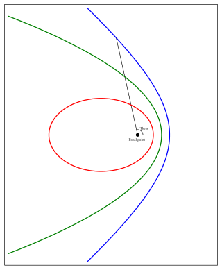
In celestial mechanics, a Kepler orbit is the motion of one body relative to another, as an ellipse, parabola, or hyperbola, which forms a two-dimensional orbital plane in three-dimensional space. A Kepler orbit can also form a straight line. It considers only the point-like gravitational attraction of two bodies, neglecting perturbations due to gravitational interactions with other objects, atmospheric drag, solar radiation pressure, a non-spherical central body, and so on. It is thus said to be a solution of a special case of the two-body problem, known as the Kepler problem. As a theory in classical mechanics, it also does not take into account the effects of general relativity. Keplerian orbits can be parametrized into six orbital elements in various ways.

Solution of triangles is the main trigonometric problem of finding the characteristics of a triangle, when some of these are known. The triangle can be located on a plane or on a sphere. Applications requiring triangle solutions include geodesy, astronomy, construction, and navigation.

<span class="mw-page-title-main">Trammel of Archimedes</span> Ellipse-drawing mechanism

A trammel of Archimedes is a mechanism that generates the shape of an ellipse. It consists of two shuttles which are confined ("trammeled") to perpendicular channels or rails and a rod which is attached to the shuttles by pivots at fixed positions along the rod.

<span class="mw-page-title-main">Quick return mechanism</span> Mechanism to produce a reciprocating motion with different speeds in opposing directions

A quick return mechanism is an apparatus to produce a reciprocating motion in which the time taken for travel in return stroke is less than in the forward stroke. It is driven by a circular motion source and uses a system of links with three turning pairs and a sliding pair. A quick-return mechanism is a subclass of a slider-crank linkage, with an offset crank.

References

  1. Hartenberg, R.S. & J. Denavit (1964) Kinematic synthesis of linkages, New York: McGraw-Hill, online link from Cornell University.
  2. Design of Machinery 3/e, Robert L. Norton, 2 May 2003, McGraw Hill. ISBN   0-07-247046-1
  3. Myszka, David (2012). Machines and Mechanisms: Applied Kinematic Analysis. New Jersey: Pearson Education. ISBN   978-0-13-215780-3.
  4. J. M. McCarthy and G. S. Soh, Geometric Design of Linkages, 2nd Edition, Springer 2010