Object diagram

Last updated
Example of an Object diagram. Object diagram.png
Example of an Object diagram.

An object diagram in the Unified Modeling Language (UML), is a diagram that shows a complete or partial view of the structure of a modeled system at a specific time.

Unified Modeling Language general-purpose, developmental, modeling language in the field of software engineering

The Unified Modeling Language (UML) is a general-purpose, developmental, modeling language in the field of software engineering that is intended to provide a standard way to visualize the design of a system.

Diagram plan, drawing, sketch or outline to show how something works or the relationships between the parts of a whole

A diagram is a symbolic representation of information according to visualization technique. Diagrams have been used since ancient times, but became more prevalent during the Enlightenment. Sometimes, the technique uses a three-dimensional visualization which is then projected onto a two-dimensional surface. The word graph is sometimes used as a synonym for diagram.

A system is a group of interacting or interrelated entities that form a unified whole. A system is delineated by its spatial and temporal boundaries, surrounded and influenced by its environment, described by its structure and purpose and expressed in its functioning.

Contents

Overview

In the Unified Modeling Language (UML), an object diagram focuses on some particular set of objects and attributes, and the links between these instances. A correlated set of object diagrams provides insight into how an arbitrary view of a system is expected to evolve over time. In early UML specifications the object diagram is described as:

In computer science, an object can be a variable, a data structure, a function, or a method, and as such, is a value in memory referenced by an identifier.

In computing, an attribute is a specification that defines a property of an object, element, or file. It may also refer to or set the specific value for a given instance of such. For clarity, attributes should more correctly be considered metadata. An attribute is frequently and generally a property of a property. However, in actual usage, the term attribute can and is often treated as equivalent to a property depending on the technology being discussed. An attribute of an object usually consists of a name and a value; of an element, a type or class name; of a file, a name and extension.

"An object diagram is a graph of instances, including objects and data values. A static object diagram is an instance of a class diagram; it shows a snapshot of the detailed state of a system at a point in time. The use of object diagrams is fairly limited, namely to show examples of data structure." [1] [2]

The latest UML 2.5 specification does not explicitly define object diagrams, [3] but provides a notation for instances of classifiers. [4]

Object diagrams and class diagrams are closely related [5] and use almost identical notation. [6] Both diagrams are meant to visualize static structure of a system. While class diagrams show classes, object diagrams display instances of classes (objects). [7] Object diagrams are more concrete than class diagrams. They are often used to provide examples or act as test cases for class diagrams. Only aspects of current interest in a model are typically shown on an object diagram.

In object-oriented programming, a class is an extensible program-code-template for creating objects, providing initial values for state and implementations of behavior. In many languages, the class name is used as the name for the class, the name for the default constructor of the class, and as the type of objects generated by instantiating the class; these distinct concepts are easily conflated.

Class diagram

In software engineering, a class diagram in the Unified Modeling Language (UML) is a type of static structure diagram that describes the structure of a system by showing the system's classes, their attributes, operations, and the relationships among objects.

Object diagram topics

Instance specifications

Each object and link on an object diagram is represented by an InstanceSpecification. This can show an object's classifier (e.g. an abstract or concrete class) and instance name, as well as attributes and other structural features using slots. Each slot corresponds to a single attribute or feature, and may include a value for that entity.

The name on an instance specification optionally shows an instance name, a ':' separator, and optionally one or more classifier names separated by commas. The contents of slots, if any, are included below the names, in a separate attribute compartment. A link is shown as a solid line, and represents an instance of an association.

In object-oriented programming, association defines a relationship between classes of objects that allows one object instance to cause another to perform an action on its behalf. This relationship is structural, because it specifies that objects of one kind are connected to objects of another and does not represent behaviour.

Object diagram example

Initially, when n=2, and f(n-2) = 0, and f(n-1) = 1, then f(n) = 0 + 1 = 1. Object Diagram Initial.png
Initially, when n=2, and f(n-2) = 0, and f(n-1) = 1, then f(n) = 0 + 1 = 1.

Consider one possible way of modeling production of Fibonacci sequence.

In the first UML object diagram on the right, the instance in the leftmost instance specification is named v1, has IndependentVariable as its classifier, plays the NMinus2 role within the FibonacciSystem, and has a slot for the val attribute with a value of 0. The second object is named v2, is of class IndependentVariable, plays the NMinus1 role, and has val = 1. The DependentVariable object is named v3, and plays the N role. The topmost instance, an anonymous instance specification, has FibonacciFunction as its classifier, and may have an instance name, a role, and slots, but these are not shown here. The diagram also includes three named links, shown as lines. Links are instances of an association.

After the first iteration, when n = 3, and f(n-2) = 1, and f(n-1) = 1, then f(n) = 1 + 1 = 2. Object Diagram 2.png
After the first iteration, when n = 3, and f(n-2) = 1, and f(n-1) = 1, then f(n) = 1 + 1 = 2.

In the second diagram, at a slightly later point in time, the IndependentVariable and DependentVariable objects are the same, but the slots for the val attribute have different values. The role names are not shown here.

After several more iterations, when n = 7, and f(n-2) = 5, and f(n-1) = 8, then f(n) = 5 + 8 = 13. Object Diagram 1.png
After several more iterations, when n = 7, and f(n-2) = 5, and f(n-1) = 8, then f(n) = 5 + 8 = 13.

In the last object diagram, a still later snapshot, the same three objects are involved. Their slots have different values. The instance and role names are not shown here.

Usage

If you are using a UML modeling tool, you will typically draw object diagrams using some other diagram type, such as on a class diagram. An object instance may be called an instance specification or just an instance. A link between instances is generally referred to as a link. Other UML entities, such as an aggregation or composition symbol (a diamond) may also appear on an object diagram.

Related Research Articles

Object-modeling language

An object-modeling language is a standardized set of symbols used to model a software system using an object-oriented framework. The symbols can be either informal or formal ranging from predefined graphical templates to formal object models defined by grammars and specifications.

Prototype-based programming is a style of object-oriented programming in which behaviour reuse is performed via a process of reusing existing objects via delegation that serve as prototypes. This model can also be known as prototypal, prototype-oriented,classless, or instance-based programming. Delegation is the language feature that supports prototype-based programming.

Data model abstract model for organizing data; abstract model that organizes elements of data and standardizes how they relate to one another and to properties of the real world entities

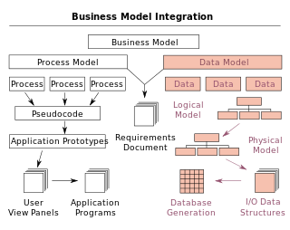
A data model is an abstract model that organizes elements of data and standardizes how they relate to one another and to properties of the real world entities. For instance, a data model may specify that the data element representing a car be composed of a number of other elements which, in turn, represent the color and size of the car and define its owner.

In object-oriented programming, a metaclass is a class whose instances are classes. Just as an ordinary class defines the behavior of certain objects, a metaclass defines the behavior of certain classes and their instances. Not all object-oriented programming languages support metaclasses. Among those that do, the extent to which metaclasses can override any given aspect of class behavior varies. Metaclasses can be implemented by having classes be first-class citizen, in which case a metaclass is simply an object that constructs classes. Each language has its own metaobject protocol, a set of rules that govern how objects, classes, and metaclasses interact.

Entity–relationship model describes inter-related things of interest in a specific domain of knowledge;composed of entity types (which classify the things of interest) and specifies relationships that can exist between instances of those entity types

An entity–relationship model describes interrelated things of interest in a specific domain of knowledge. A basic ER model is composed of entity types and specifies relationships that can exist between entities.

A stereotype is one of three types of extensibility mechanisms in the Unified Modeling Language (UML), the other two being tags and constraints. They allow designers to extend the vocabulary of UML in order to create new model elements, derived from existing ones, but that have specific properties that are suitable for a particular domain or otherwise specialized usage. The nomenclature is derived from the original meaning of stereotype, used in printing. For example, when modeling a network you might need to have symbols for representing routers and hubs. By using stereotyped nodes you can make these things appear as primitive building blocks.

Object Process Methodology modelling language and methodology for capturing knowledge and designing systems

Object Process Methodology (OPM) is a conceptual modeling language and methodology for capturing knowledge and designing systems, specified as ISO/PAS 19450. Based on a minimal universal ontology of stateful objects and processes that transform them, OPM can be used to formally specify the function, structure, and behavior of artificial and natural systems in a large variety of domains.

Sequence diagram

A sequence diagram shows object interactions arranged in time sequence. It depicts the objects and classes involved in the scenario and the sequence of messages exchanged between the objects needed to carry out the functionality of the scenario. Sequence diagrams are typically associated with use case realizations in the Logical View of the system under development. Sequence diagrams are sometimes called event diagrams or event scenarios.

UML color standards are a set of four colors associated with Unified Modeling Language (UML) diagrams. The coloring system indicates which of several archetypes apply to the UML object. UML typically identifies a stereotype with a bracketed comment for each object identifying whether it is a class, interface, etc.

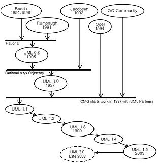
This glossary of Unified Modeling Language terms covers all versions of UML. Individual entries will point out any distinctions that exist between versions.

Executable UML is both a software development method and a highly abstract software language. It was described for the first time in 2002 in the book "Executable UML: A Foundation for Model-Driven Architecture". The language "combines a subset of the UML graphical notation with executable semantics and timing rules." The Executable UML method is the successor to the Shlaer–Mellor method.

Object-oriented design is the process of planning a system of interacting objects for the purpose of solving a software problem. It is one approach to software design.

Composite structure diagram in the Unified Modeling Language (UML) is a type of static structure diagram, that shows the internal structure of a class and the collaborations that this structure makes possible.

ECO , is a software framework suited for Domain-Driven-Design (DDD) from Capable Objects AB, designed to increase productivity by utilizing facilities such as Object-relational mapping (ORM) for persisting domain objects, UML models for domain classes and executable State Machines for behavior control defined in UML notation. The ECO framework is intended to be an all-in-one solution for enterprise development and includes in-memory transactions and Undo/Redo functionality as well as easy binding with UI layer. ECO unites ORM framework and UML modeling tools with instant code generation and an OCL expression evaluator for simplified in-memory and DB queries, business rules and other useful facilities.

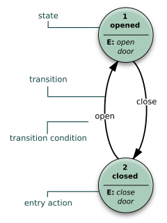
UML state machine, also known as UML statechart, is a significantly enhanced realization of the mathematical concept of a finite automaton in computer science applications as expressed in the Unified Modeling Language (UML) notation.

Applications of UML

UML is a modeling language used by software developers. UML can be used to develop diagrams and provide users with ready-to-use, expressive modeling examples. Some UML tools generate program language code from UML. UML can be used for modeling a system independent of a platform language. UML is a graphical language for visualizing, specifying, constructing, and documenting information about software-intensive systems. UML gives a standard way to write a system model, covering conceptual ideas. With an understanding of modeling, the use and application of UML can make the software development process more efficient.

Umple language for both object-oriented programming and modelling with class diagrams and state diagrams

Umple is a language for both object-oriented programming and modelling with class diagrams and state diagrams. The name Umple is a portmanteau of "UML", "ample" and "Simple", indicating that it is designed to provide ample features to extend programming languages with UML capabilities.

References

  1. Object Management Group (2001) UML specification 1.4, September 2001
  2. Anne Banks Pidduck, John Mylopoulos, Carson C. Woo (2002) Advanced Information Systems Engineering. p.776.
  3. Classification of UML 2.5 Diagrams on uml-diagrams.org. Retrieved Dec 7, 2012
  4. Object Management Group (2015)UML specification 2.5, Section 9.8.4 on notation of InstanceSpecification, March 2015
  5. Marcus Fontoura, Wolfgang Pree & Bernhard Rumpe (2002) The UML profile for framework architectures. p.19
  6. Kassem A. Saleh (2009) Software Engineering. p.47
  7. Bianca Scholten (2007) The Road to Integration: A Guide to Applying the ISA-95 Standard in Manufacturing. p.155