
| UML diagram types |
|---|
| Structural UML diagrams |
| Behavioral UML diagrams |
A package diagram in the Unified Modeling Language depicts the dependencies between the packages that make up a model.
| UML diagram types |
|---|
| Structural UML diagrams |
| Behavioral UML diagrams |
A package diagram in the Unified Modeling Language depicts the dependencies between the packages that make up a model.
In addition to the standard UML Dependency relationship, there are two special types of dependencies defined between packages:
A package import is "a relationship between an importing namespace and a package, indicating that the importing namespace adds the names of the members of the package to its own namespace." [1] By default, an unlabeled dependency between two packages is interpreted as a package import relationship. In this relationship, elements within the target package will be imported into the source package.
A package merge is "a directed relationship between two packages, that indicates that the contents of the two packages are to be combined. It is very similar to Generalisation in the sense that the source element conceptually adds the characteristics of the target element to its own characteristics resulting in an element that combines the characteristics of both" [2] In this relationship, if an element exists within both the source package and the target package, then the source element's definition will be expanded to include the target element's definition.

Package diagrams can use packages containing use cases to illustrate the functionality of a software system.
Package diagrams can use packages that represent the different layers of a software system to illustrate the layered architecture of a software system. The dependencies between these packages can be adorned with labels / stereotypes to indicate the communication mechanism between the layers.
The unified modeling language (UML) is a general-purpose visual modeling language that is intended to provide a standard way to visualize the design of a system.
A stereotype is one of three types of extensibility mechanisms in the Unified Modeling Language (UML), the other two being tags and constraints. They allow designers to extend the vocabulary of UML in order to create new model elements, derived from existing ones, but that have specific properties that are suitable for a particular domain or otherwise specialized usage. The nomenclature is derived from the original meaning of stereotype, used in printing. For example, when modeling a network you might need to have symbols for representing routers and hubs. By using stereotyped nodes you can make these things appear as primitive building blocks.

In software engineering, a sequence diagram shows process interactions arranged in time sequence. This diagram depicts the processes and objects involved and the sequence of messages exchanged as needed to carry out the functionality. Sequence diagrams are typically associated with use case realizations in the 4+1 architectural view model of the system under development. Sequence diagrams are sometimes called event diagrams or event scenarios.

In software engineering, a class diagram in the Unified Modeling Language (UML) is a type of static structure diagram that describes the structure of a system by showing the system's classes, their attributes, operations, and the relationships among objects.
StarUML is a software engineering tool for system modeling using the Unified Modeling Language, as well as Systems Modeling Language, and classical modeling notations. It is published by MKLabs and is available on Windows, Linux and MacOS.
Glossary of Unified Modeling Language (UML) terms provides a compilation of terminology used in all versions of UML, along with their definitions. Any notable distinctions that may exist between versions are noted with the individual entry it applies to.
Executable UML is both a software development method and a highly abstract software language. It was described for the first time in 2002 in the book "Executable UML: A Foundation for Model-Driven Architecture". The language "combines a subset of the UML graphical notation with executable semantics and timing rules." The Executable UML method is the successor to the Shlaer–Mellor method.
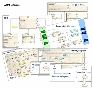
The systems modeling language (SysML) is a general-purpose modeling language for systems engineering applications. It supports the specification, analysis, design, verification and validation of a broad range of systems and systems-of-systems.
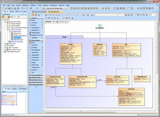
MagicDraw is a proprietary visual UML, SysML, BPMN, and UPDM modeling tool with team collaboration support.
Composite structure diagram in the Unified Modeling Language (UML) is a type of static structure diagram, that shows the internal structure of a class and the collaborations that this structure makes possible.
A profile in the Unified Modeling Language (UML) provides a generic extension mechanism for customizing UML models for particular domains and platforms. Extension mechanisms allow refining standard semantics in strictly additive manner, preventing them from contradicting standard semantics.
In the Unified Modeling Language (UML), a Dependency is a relationship that shows that an element, or set of elements, requires other model elements for their specification or implementation. The element is dependent upon the independent element, called the supplier. Two or more elements in this relationship are called tuples.
Knowledge Discovery Metamodel (KDM) is a publicly available specification from the Object Management Group (OMG). KDM is a common intermediate representation for existing software systems and their operating environments, that defines common metadata required for deep semantic integration of Application Lifecycle Management tools. KDM was designed as the OMG's foundation for software modernization, IT portfolio management and software assurance. KDM uses OMG's Meta-Object Facility to define an XMI interchange format between tools that work with existing software as well as an abstract interface (API) for the next-generation assurance and modernization tools. KDM standardizes existing approaches to knowledge discovery in software engineering artifacts, also known as software mining.

A component in the Unified Modeling Language represents a modular part of a system that encapsulates the state and behavior of a number of classifiers. Its behavior is defined in terms of provided and required interfaces, is self-contained, and substitutable. A number of UML standard stereotypes exist that apply to components.

An artifact in the Unified Modeling Language (UML) is the specification of a physical piece of information that is used or produced by a software development process, or by deployment and operation of a system."

A package in the Unified Modeling Language is used "to group elements, and to provide a namespace for the grouped elements". A package may contain other packages, thus providing for a hierarchical organization of packages.
UML state machine, also known as UML statechart, is an extension of the mathematical concept of a finite automaton in computer science applications as expressed in the Unified Modeling Language (UML) notation.
UML is a modeling language used by software developers. UML can be used to develop diagrams and provide users (programmers) with ready-to-use, expressive modeling examples. Some UML tools generate program language code from UML. UML can be used for modeling a system independent of a platform language. UML is a graphical language for visualizing, specifying, constructing, and documenting information about software-intensive systems. UML gives a standard way to write a system model, covering conceptual ideas. With an understanding of modeling, the use and application of UML can make the software development process more efficient.
In the Unified Modeling Language (UML), an Element is an abstract class with no superclass. It is used as the superclass or base class, as known by object oriented programmers, for all the metaclasses in the UML infrastructure library. All other elements in the UML inherit, directly or indirectly from Element. An Element has a derived composition association to itself to support the general capability for elements to own other elements. As such, it has no additional attributes as part of its specification.
The Interaction Flow Modeling Language (IFML) is a standardized modeling language in the field of software engineering. IFML includes a set of graphic notations to create visual models of user interactions and front-end behavior in software systems.
This article needs additional citations for verification .(February 2009) |
| Actors |
|  | |||||||||||
|---|---|---|---|---|---|---|---|---|---|---|---|---|---|
| Concepts |
| ||||||||||||
| Diagrams |
| ||||||||||||
| Derived languages | |||||||||||||
| Other topics | |||||||||||||