Class diagram

Last updated
Hierarchy of UML 2.5 Diagrams, shown as a class diagram. The individual classes are represented just with one compartment, but they often contain up to three compartments. UML diagrams overview.svg
Hierarchy of UML 2.5 Diagrams, shown as a class diagram. The individual classes are represented just with one compartment, but they often contain up to three compartments.

In software engineering, a class diagram in the Unified Modeling Language (UML) is a type of static structure diagram that describes the structure of a system by showing the system's classes, their attributes, operations (or methods), and the relationships among objects.

Contents

The class diagram is the main building block of object-oriented modeling. It is used for general conceptual modeling of the structure of the application, and for detailed modeling, translating the models into programming code. Class diagrams can also be used for data modeling. [1] The classes in a class diagram represent both the main elements, interactions in the application, and the classes to be programmed.

In the diagram, classes are represented with boxes that contain three compartments:

A class with three compartments. BankAccount1.svg
A class with three compartments.

In the design of a system, a number of classes are identified and grouped together in a class diagram that helps to determine the static relations between them. In detailed modeling, the classes of the conceptual design are often split into subclasses. [2]

In order to further describe the behavior of systems, these class diagrams can be complemented by a state diagram or UML state machine. [3]

Members

UML provides mechanisms to represent class members, such as attributes and methods, and additional information about them like constructors.

Visibility

To specify the visibility of a class member (i.e. any attribute or method), these notations must be placed before the members' name: [4]

+Public
-Private
#Protected
~Package

A derived property is a property whose value (or values) is produced or computed from other information, for example, by using values of other properties.

A derived property is shown with its name preceded by a forward slash '/'. [5]

Scope

The UML specifies two types of scope for members: instance and class, and the latter is represented by underlined names. [6]

To indicate a classifier scope for a member, its name must be underlined. Otherwise, instance scope is assumed by default.

Relationships

UML relations notation Uml classes en.svg
UML relations notation

A relationship is a general term covering the specific types of logical connections found on class and object diagrams. UML defines the following relationships:

Instance-level relationships

Dependency

A dependency is a type of association where there is a semantic connection between dependent and independent model elements. [7] It exists between two elements if changes to the definition of one element (the server or target) may cause changes to the other (the client or source). This association is uni-directional. A dependency is displayed as a dashed line with an open arrow that points from the client to the supplier.

Association

Class diagram example of association between two classes UML role example.gif
Class diagram example of association between two classes

An association represents a family of structural links. A binary association is represented as a solid line between two classes. A reflexive association is a binary association between the class and itself. An association between more than two classes is represented as a diamond connected with a solid line to each of the associated classes. An association between three classes is a ternary association. An association between more classes is called an n-ary association.

An association can be named, and the ends of an association can be adorned with role names, aggregation indicators, multiplicity, visibility, navigability and other properties. The dot notation for example allows to represent with a little dot on the side of one class that the association end is owned by the other side. [8]

There are three types of association: simple association, shared aggregation, composite aggregation (composition). An association can be navigable in one or more directions. The navigability does not have to be explicitly specified. An open-headed arrow on the side of a class documents that the class can be reached efficiently at run-time from the opposite side. A unidirectional navigation is shown with a little cross on the association line on the side of the class that cannot be reached. For instance, a flight class is associated with a plane class bi-directionally.

Aggregation

Class diagram showing Aggregation between two classes. Here, a Professor 'has a' class to teach. KP-UML-Aggregation-20060420.svg
Class diagram showing Aggregation between two classes. Here, a Professor 'has a' class to teach.

Aggregation is a variant of the "has a" association relationship; aggregation is more specific than association. It is an association that represents a part-whole or part-of relationship. As shown in the image, a Professor 'has a' class to teach. As a type of association, an aggregation can be named and have the same adornments that an association can. However, an aggregation may not involve more than two classes; it must be a binary association. Furthermore, there is hardly a difference between aggregations and associations during implementation, and the diagram may skip aggregation relations altogether. [9]

Aggregation can occur when a class is a collection or container of other classes, but the contained classes do not have a strong lifecycle dependency on the container. The contents of the container still exist when the container is destroyed.

In UML, it is graphically represented as a hollow diamond shape on the containing class with a single line that connects it to the contained class. The aggregate is semantically an extended object that is treated as a unit in many operations, although physically it is made of several lesser objects.

Composition

Two class diagrams. The diagram on top shows Composition between two classes: A Car has exactly one Carburetor, and a Carburetor is a part of one Car. Carburetors cannot exist as separate parts, detached from a specific car. The diagram on bottom shows Aggregation between two classes: A Pond has zero or more Ducks, and a Duck has at most one Pond (at a time). Duck can exist separately from a Pond, e.g. it can live near a lake. When we destroy a Pond we usually do not kill all the Ducks. AggregationAndComposition-edited.svg
Two class diagrams. The diagram on top shows Composition between two classes: A Car has exactly one Carburetor, and a Carburetor is a part of one Car. Carburetors cannot exist as separate parts, detached from a specific car. The diagram on bottom shows Aggregation between two classes: A Pond has zero or more Ducks, and a Duck has at most one Pond (at a time). Duck can exist separately from a Pond, e.g. it can live near a lake. When we destroy a Pond we usually do not kill all the Ducks.

The composite aggregation (colloquially called composition) relationship is a stronger form of aggregation where the aggregate controls the lifecycle of the elements it aggregates. The graphical representation is a filled diamond shape on the containing class end of the line that connect contained class(es) to the containing class.

Differences between Composition and Aggregation

Composition relationship
1. When attempting to represent real-world whole-part relationships, e.g. an engine is a part of a car.
2. When the container is destroyed, the contents are also destroyed, e.g. a university and its departments.
Aggregation relationship
1. When representing a software or database relationship, e.g. car model engine ENG01 is part of a car model CM01, as the engine, ENG01, maybe also part of a different car model. [10]
2. When the container is destroyed, the contents are usually not destroyed, e.g. a professor has students; when the professor leaves the university the students do not leave along with the professor.

Thus the aggregation relationship is often "catalog" containment to distinguish it from composition's "physical" containment. UML 2 does not specify any semantic for the aggregation compared to the simple association.

Class-level relationships

Generalization/Inheritance

Class diagram showing generalization between the superclass Person and the two subclasses Student and Professor KP-UML-Generalization-20060325.svg
Class diagram showing generalization between the superclass Person and the two subclasses Student and Professor

It indicates that one of the two related classes (the subclass) is considered to be a specialized form of the other (the super type) and the superclass is considered a Generalization of the subclass. In practice, this means that any instance of the subtype is also an instance of the superclass. An exemplary tree of generalizations of this form is found in biological classification: humans are a subclass of simian, which is a subclass of mammal, and so on. The relationship is most easily understood by the phrase 'an A is a B' (a human is a mammal, a mammal is an animal).

The UML graphical representation of a Generalization is a hollow triangle shape on the superclass end of the line (or tree of lines) that connects it to one or more subtypes.

   symbolic of realization           (subclass) _______▻ (superclass)

The generalization relationship is also known as the inheritance or "is a" relationship.

The superclass (base class) in the generalization relationship is also known as the "parent", superclass, base class, or base type.

The subtype in the specialization relationship is also known as the "child", subclass, derived class, derived type, inheriting class, or inheriting type.

Note that this relationship bears no resemblance to the biological parent–child relationship: the use of these terms is extremely common, but can be misleading.

A is a type of B
For example, "an oak is a type of tree", "an automobile is a type of vehicle"

Generalization can only be shown on class diagrams and on use case diagrams.

Realization/Implementation

In UML modelling, a realization relationship is a relationship between two model elements, in which one model element (the client) realizes (implements or executes) the behavior that the other model element (the supplier) specifies.

The UML graphical representation of a Realization is a hollow triangle shape on the interface end of the dashed line (or tree of lines) that connects it to one or more implementers. A plain arrow head is used on the interface end of the dashed line that connects it to its users. In component diagrams, the ball-and-socket graphic convention is used (implementors expose a ball or lollipop, whereas users show a socket). Realizations can only be shown on class or component diagrams. A realization is a relationship between classes, interfaces, components and packages that connects a client element with a supplier element. A realization relationship between classes/components and interfaces shows that the class/component realizes the operations offered by the interface.

   symbolic of realization           (implementer) -------▻ (interface)

General relationship

Class diagram showing dependency between "Car" class and "Wheel" class (An even clearer example would be "Car depends on Wheel", because Car already aggregates (and not just uses) Wheel) Class Dependency.png
Class diagram showing dependency between "Car" class and "Wheel" class (An even clearer example would be "Car depends on Wheel", because Car already aggregates (and not just uses) Wheel)

Dependency

Dependency can be a weaker form of bond that indicates that one class depends on another because it uses it at some point in time. One class depends on another if the independent class is a parameter variable or local variable of a method of the dependent class. Sometimes the relationship between two classes is very weak. They are not implemented with member variables at all. Rather they might be implemented as member function arguments.

Multiplicity

This association relationship indicates that (at least) one of the two related classes make reference to the other. This relationship is usually described as "A has a B" (a mother cat has kittens, kittens have a mother cat).

The UML representation of an association is a line connecting the two associated classes. At each end of the line there is optional notation. For example, we can indicate, using an arrowhead that the pointy end is visible from the arrow tail. We can indicate ownership by the placement of a ball, the role the elements of that end play by supplying a name for the role, and the multiplicity of instances of that entity (the range of number of objects that participate in the association from the perspective of the other end).

0No instances (rare)
0..1No instances, or one instance
1Exactly one instance
1..1Exactly one instance
0..*Zero or more instances
*Zero or more instances
1..*One or more instances

Analysis stereotypes

EntityControlBoundary Pattern.jpg

Entities

Entity classes model long-lived information handled by the system, and sometimes the behavior associated with the information. They should not be identified as database tables or other data-stores.

They are drawn as circles with a short line attached to the bottom of the circle. Alternatively, they can be drawn as normal classes with the «entity» stereotype notation above the class name.

See also

Related diagrams

Related Research Articles

In object-oriented programming, a class is an extensible program-code-template for creating objects, providing initial values for state and implementations of behavior.

<span class="mw-page-title-main">Unified Modeling Language</span> Software system design modeling tool

The unified modeling language (UML) is a general-purpose visual modeling language that is intended to provide a standard way to visualize the design of a system.

<span class="mw-page-title-main">Object-modeling technique</span> Object modeling approach for software modeling

The object-modeling technique (OMT) is an object modeling approach for software modeling and designing. It was developed around 1991 by Rumbaugh, Blaha, Premerlani, Eddy and Lorensen as a method to develop object-oriented systems and to support object-oriented programming. OMT describes object model or static structure of the system.

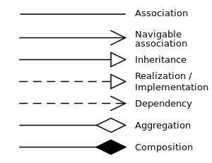
In database design, object-oriented programming and design, has-a is a composition relationship where one object "belongs to" another object, and behaves according to the rules of ownership. In simple words, has-a relationship in an object is called a member field of an object. Multiple has-a relationships will combine to form a possessive hierarchy.

In knowledge representation and ontology components, including for object-oriented programming and design, is-a is a subsumptive relationship between abstractions, wherein one class A is a subclass of another class B . In other words, type A is a subtype of type B when A's specification implies B's specification. That is, any object that satisfies A's specification also satisfies B's specification, because B's specification is weaker.

In object-oriented programming, a metaclass is a class whose instances are also classes. Just as an ordinary class defines the behavior of certain objects, a metaclass defines the behavior of certain classes and their instances. Not all object-oriented programming languages support metaclasses. Among those that do, the extent to which metaclasses can override any given aspect of class behavior varies. Metaclasses can be implemented by having classes be first-class citizens, in which case a metaclass is simply an object that constructs classes. Each language has its own metaobject protocol, a set of rules that govern how objects, classes, and metaclasses interact. Metaclasses can be used, for example, to generate code automatically, or in developing frameworks.

<span class="mw-page-title-main">Entity–relationship model</span> Model or diagram describing interrelated things

An entity–relationship model describes interrelated things of interest in a specific domain of knowledge. A basic ER model is composed of entity types and specifies relationships that can exist between entities.

A stereotype is one of three types of extensibility mechanisms in the Unified Modeling Language (UML), the other two being tags and constraints. They allow designers to extend the vocabulary of UML in order to create new model elements, derived from existing ones, but that have specific properties that are suitable for a particular domain or otherwise specialized usage. The nomenclature is derived from the original meaning of stereotype, used in printing. For example, when modeling a network you might need to have symbols for representing routers and hubs. By using stereotyped nodes you can make these things appear as primitive building blocks.

In computer science, object composition and object aggregation are closely related ways to combine objects or data types into more complex ones. In conversation the distinction between composition and aggregation is often ignored. Common kinds of compositions are objects used in object-oriented programming, tagged unions, sets, sequences, and various graph structures. Object compositions relate to, but are not the same as, data structures.

In object-oriented programming, inheritance is the mechanism of basing an object or class upon another object or class, retaining similar implementation. Also defined as deriving new classes from existing ones such as super class or base class and then forming them into a hierarchy of classes. In most class-based object-oriented languages like C++, an object created through inheritance, a "child object", acquires all the properties and behaviors of the "parent object", with the exception of: constructors, destructors, overloaded operators and friend functions of the base class. Inheritance allows programmers to create classes that are built upon existing classes, to specify a new implementation while maintaining the same behaviors, to reuse code and to independently extend original software via public classes and interfaces. The relationships of objects or classes through inheritance give rise to a directed acyclic graph.

<span class="mw-page-title-main">Package diagram</span>

A package diagram in the Unified Modeling Language depicts the dependencies between the packages that make up a model.

Glossary of Unified Modeling Language (UML) terms provides a compilation of terminology used in all versions of UML, along with their definitions. Any notable distinctions that may exist between versions are noted with the individual entry it applies to.

Executable UML is both a software development method and a highly abstract software language. It was described for the first time in 2002 in the book "Executable UML: A Foundation for Model-Driven Architecture". The language "combines a subset of the UML graphical notation with executable semantics and timing rules." The Executable UML method is the successor to the Shlaer–Mellor method.

<span class="mw-page-title-main">MagicDraw</span> Systems modelling software

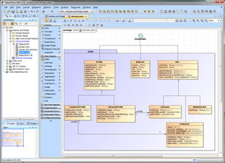
MagicDraw is a proprietary visual UML, SysML, BPMN, and UPDM modeling tool with team collaboration support.

Object-oriented design (OOD) is the process of planning a system of interacting objects for the purpose of solving a software problem. It is a method for software design. By defining classes and their functionality for their children, each object can run the same implementation of the class with its own state.

<span class="mw-page-title-main">Object diagram</span> Diagram showing the structure of objects in a system

In object-oriented programming, an object diagram in the Unified Modeling Language (UML) is a diagram that shows a complete or partial view of the structure of a modeled system at a specific time.

Composite structure diagram in the Unified Modeling Language (UML) is a type of static structure diagram, that shows the internal structure of a class and the collaborations that this structure makes possible.

In the Unified Modeling Language (UML), a Dependency is a relationship that shows that an element, or set of elements, requires other model elements for their specification or implementation. The element is dependent upon the independent element, called the supplier. Two or more elements in this relationship are called tuples.

Metadata modeling is a type of metamodeling used in software engineering and systems engineering for the analysis and construction of models applicable to and useful for some predefined class of problems.

The enhanced entity–relationship (EER) model in computer science is a high-level or conceptual data model incorporating extensions to the original entity–relationship (ER) model, used in the design of databases.

References

  1. Sparks, Geoffrey. "Database Modeling in UML" . Retrieved 8 September 2011.
  2. Flatt, Amelie; Langner, Arne; Leps, Olof (2022), "Phase I: Mapping Legal Concepts to Technical Objects" , Model-Driven Development of Akoma Ntoso Application Profiles, Cham: Springer International Publishing, pp. 13–17, doi:10.1007/978-3-031-14132-4_3, ISBN   978-3-031-14131-7 , retrieved 2023-01-07
  3. Scott W. Ambler (2009) UML 2 Class Diagrams. Webdoc 2003-2009. Accessed Dec 2, 2009
  4. UML Reference Card, Version 2.1.2, Holub Associates, August 2007, retrieved 12 March 2011
  5. "UML derived property is property which value is produced or computed from other information, for example, by using other properties". www.uml-diagrams.org. Retrieved 2019-01-24.
  6. OMG Unified Modeling Language (OMG UML) Superstructure, Version 2.3: May 2010. Retrieved 23 September 2010.
  7. Fowler (2003) UML Distilled: A Brief Guide to the Standard Object Modeling Language
  8. Selic, Bran (2013-04-18). "Getting it right on the dot" (PDF). www.omg.org. Object Management Group . Retrieved 2023-11-26.
  9. "UML Tutorial part 1: class diagrams" (PDF). Archived from the original (PDF) on 2007-01-03. Retrieved 2015-07-18.
  10. Goodwin, David. "Modelling and Simulation, p. 26" (PDF). The University of Warwick. Retrieved 28 November 2015.