Related Research Articles
An electronic oscillator is an electronic circuit that produces a periodic, oscillating or alternating current (AC) signal, usually a sine wave, square wave or a triangle wave, powered by a direct current (DC) source. Oscillators are found in many electronic devices, such as radio receivers, television sets, radio and television broadcast transmitters, computers, computer peripherals, cellphones, radar, and many other devices.

An amplifier, electronic amplifier or (informally) amp is an electronic device that can increase the magnitude of a signal. It is a two-port electronic circuit that uses electric power from a power supply to increase the amplitude of a signal applied to its input terminals, producing a proportionally greater amplitude signal at its output. The amount of amplification provided by an amplifier is measured by its gain: the ratio of output voltage, current, or power to input. An amplifier is defined as a circuit that has a power gain greater than one.

Feedback occurs when outputs of a system are routed back as inputs as part of a chain of cause-and-effect that forms a circuit or loop. The system can then be said to feed back into itself. The notion of cause-and-effect has to be handled carefully when applied to feedback systems:
Simple causal reasoning about a feedback system is difficult because the first system influences the second and second system influences the first, leading to a circular argument. This makes reasoning based upon cause and effect tricky, and it is necessary to analyze the system as a whole. As provided by Webster, feedback in business is the transmission of evaluative or corrective information about an action, event, or process to the original or controlling source.

An operational amplifier is a DC-coupled high-gain electronic voltage amplifier with a differential input and, usually, a single-ended output. In this configuration, an op amp produces an output potential that is typically 100,000 times larger than the potential difference between its input terminals. The operational amplifier traces its origin and name to analog computers, where they were used to perform mathematical operations in linear, non-linear, and frequency-dependent circuits.

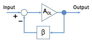
A negative-feedback amplifier is an electronic amplifier that subtracts a fraction of its output from its input, so that negative feedback opposes the original signal. The applied negative feedback can improve its performance and reduces sensitivity to parameter variations due to manufacturing or environment. Because of these advantages, many amplifiers and control systems use negative feedback.

Positive feedback is a process that occurs in a feedback loop which exacerbates the effects of a small disturbance. That is, the effects of a perturbation on a system include an increase in the magnitude of the perturbation. That is, A produces more of B which in turn produces more of A. In contrast, a system in which the results of a change act to reduce or counteract it has negative feedback. Both concepts play an important role in science and engineering, including biology, chemistry, and cybernetics.

A regenerative circuit is an amplifier circuit that employs positive feedback. Some of the output of the amplifying device is applied back to its input to add to the input signal, increasing the amplification. One example is the Schmitt trigger, but the most common use of the term is in RF amplifiers, and especially regenerative receivers, to greatly increase the gain of a single amplifier stage.

In electronics, a common-emitter amplifier is one of three basic single-stage bipolar-junction-transistor (BJT) amplifier topologies, typically used as a voltage amplifier. It offers high current gain, medium input resistance and a high output resistance. The output of a common emitter amplifier is 180 degrees out of phase to the input signal.
Linear electronic oscillator circuits, which generate a sinusoidal output signal, are composed of an amplifier and a frequency selective element, a filter. A linear oscillator circuit which uses an RC network, a combination of resistors and capacitors, for its frequency selective part is called an RC oscillator.

A ring oscillator is a device composed of an odd number of NOT gates in a ring, whose output oscillates between two voltage levels, representing true and false. The NOT gates, or inverters, are attached in a chain and the output of the last inverter is fed back into the first.

A class-D amplifier or switching amplifier is an electronic amplifier in which the amplifying devices operate as electronic switches, and not as linear gain devices as in other amplifiers. They operate by rapidly switching back and forth between the supply rails, using pulse-width modulation, pulse-density modulation, or related techniques to produce a pulse train output. This passes through a simple low-pass filter which blocks the high-frequency pulses and provides analog output current and voltage. Because they are always either in fully on or fully off modes, little energy is dissipated in the transistors and efficiency can exceed 90%.
In electronics, the Miller effect accounts for the increase in the equivalent input capacitance of an inverting voltage amplifier due to amplification of the effect of capacitance between the input and output terminals. The virtually increased input capacitance due to the Miller effect is given by
In electronics, motorboating is a type of low frequency parasitic oscillation that sometimes occurs in audio and radio equipment and often manifests itself as a sound similar to an idling motorboat engine, a "put-put-put", in audio output from speakers or earphones. It is a problem encountered particularly in radio transceivers and older vacuum tube audio systems, guitar amplifiers, PA systems and is caused by some type of unwanted feedback in the circuit. The amplifying devices in audio and radio equipment are vulnerable to a variety of feedback problems, which can cause distinctive noise in the output. The term motorboating is applied to oscillations whose frequency is below the range of hearing, from 1 to 10 hertz, so the individual oscillations are heard as pulses. Sometimes the oscillations can even be seen visually as the woofer cones in speakers slowly moving in and out.

Distributed amplifiers are circuit designs that incorporate transmission line theory into traditional amplifier design to obtain a larger gain-bandwidth product than is realizable by conventional circuits.
In electronic amplifiers, the phase margin (PM) is the difference between the phase lag φ and -180°, for an amplifier's output signal at zero dB gain - i.e. unity gain, or that the output signal has the same amplitude as the input.
In the field of electronics, a technique where part of the output of a system is used at startup can be described as bootstrapping.
A fully differential amplifier (FDA) is a DC-coupled high-gain electronic voltage amplifier with differential inputs and differential outputs. In its ordinary usage, the output of the FDA is controlled by two feedback paths which, because of the amplifier's high gain, almost completely determine the output voltage for any given input.

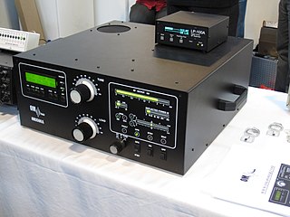
A valve RF amplifier or tube amplifier (U.S.) is a device for electrically amplifying the power of an electrical radio frequency signal.
Technical specifications and detailed information on the valve audio amplifier, including its development history.

Tube sound is the characteristic sound associated with a vacuum tube amplifier, a vacuum tube-based audio amplifier. At first, the concept of tube sound did not exist, because practically all electronic amplification of audio signals was done with vacuum tubes and other comparable methods were not known or used. After introduction of solid state amplifiers, tube sound appeared as the logical complement of transistor sound, which had some negative connotations due to crossover distortion in early transistor amplifiers. However, solid state amplifiers have been developed to be flawless and the sound is later regarded neutral compared to tube amplifiers. Thus the tube sound now means 'euphonic distortion.' The audible significance of tube amplification on audio signals is a subject of continuing debate among audio enthusiasts.
References
- ↑ Whitaker, Jerry C. (2005). The electronics handbook. CRC Press. p. 404. ISBN 978-0-8493-1889-4.
- ↑ Weber, Gerald (1994). A Desktop Reference of Hip Vintage Guitar Amps. Hal Leonard. p. 220. ISBN 978-0-9641060-0-0.
- ↑ Wanhammar, Lars (1999). DSP integrated circuits. Academic Press. p. 188. ISBN 978-0-12-734530-7.
- ↑ Richard R Spencer & Ghausi MS (2003). Introduction to electronic circuit design. Upper Saddle River NJ: Prentice Hall/Pearson Education. pp. 661. ISBN 0-201-36183-3. http://worldcat.org/isbn/0-201-36183-3.
- ↑ Araki, M., PID Control, http://www.eolss.net/ebooks/Sample%20Chapters/C18/E6-43-03-03.pdf
- ↑ P. Horowitz & W. Hill The Art of Electronics Cambridge University Press (1980) Chapter 3, relating to operational amplifiers.
- ↑ National Transportation Safety Board (27 July 2010). Collision of Two Washington Metropolitan Area Transit Authority Metrorail Trains Near Fort Totten Station (PDF). National Transportation Safety Board. p. xi. Retrieved 19 November 2020.