In physics, the cross section is a measure of the probability that a specific process will take place when some kind of radiant excitation intersects a localized phenomenon. For example, the Rutherford cross-section is a measure of probability that an alpha particle will be deflected by a given angle during an interaction with an atomic nucleus. Cross section is typically denoted σ (sigma) and is expressed in units of area, more specifically in barns. In a way, it can be thought of as the size of the object that the excitation must hit in order for the process to occur, but more exactly, it is a parameter of a stochastic process.

In optics, the refractive index of an optical medium is a dimensionless number that gives the indication of the light bending ability of that medium.
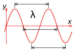
In physics, the wavelength is the spatial period of a periodic wave—the distance over which the wave's shape repeats. It is the distance between consecutive corresponding points of the same phase on the wave, such as two adjacent crests, troughs, or zero crossings, and is a characteristic of both traveling waves and standing waves, as well as other spatial wave patterns. The inverse of the wavelength is called the spatial frequency. Wavelength is commonly designated by the Greek letter lambda (λ). The term wavelength is also sometimes applied to modulated waves, and to the sinusoidal envelopes of modulated waves or waves formed by interference of several sinusoids.
The propagation constant of a sinusoidal electromagnetic wave is a measure of the change undergone by the amplitude and phase of the wave as it propagates in a given direction. The quantity being measured can be the voltage, the current in a circuit, or a field vector such as electric field strength or flux density. The propagation constant itself measures the change per unit length, but it is otherwise dimensionless. In the context of two-port networks and their cascades, propagation constant measures the change undergone by the source quantity as it propagates from one port to the next.

Magnetic circular dichroism (MCD) is the differential absorption of left and right circularly polarized (LCP and RCP) light, induced in a sample by a strong magnetic field oriented parallel to the direction of light propagation. MCD measurements can detect transitions which are too weak to be seen in conventional optical absorption spectra, and it can be used to distinguish between overlapping transitions. Paramagnetic systems are common analytes, as their near-degenerate magnetic sublevels provide strong MCD intensity that varies with both field strength and sample temperature. The MCD signal also provides insight into the symmetry of the electronic levels of the studied systems, such as metal ion sites.
In the physical sciences, the wavenumber is the spatial frequency of a wave, measured in cycles per unit distance or radians per unit distance. It is analogous to temporal frequency, which is defined as the number of wave cycles per unit time or radians per unit time.
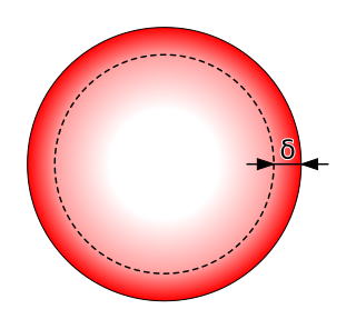
Skin effect is the tendency of an alternating electric current (AC) to become distributed within a conductor such that the current density is largest near the surface of the conductor and decreases exponentially with greater depths in the conductor. The electric current flows mainly at the "skin" of the conductor, between the outer surface and a level called the skin depth. Skin depth depends on the frequency of the alternating current; as frequency increases, current flow moves to the surface, resulting in less skin depth. Skin effect reduces the effective cross-section of the conductor and thus increases its effective resistance. Skin effect is caused by opposing eddy currents induced by the changing magnetic field resulting from the alternating current. At 60 Hz in copper, the skin depth is about 8.5 mm. At high frequencies the skin depth becomes much smaller.

Transmittance of the surface of a material is its effectiveness in transmitting radiant energy. It is the fraction of incident electromagnetic power that is transmitted through a sample, in contrast to the transmission coefficient, which is the ratio of the transmitted to incident electric field.
Self-phase modulation (SPM) is a nonlinear optical effect of light–matter interaction. An ultrashort pulse of light, when travelling in a medium, will induce a varying refractive index of the medium due to the optical Kerr effect. This variation in refractive index will produce a phase shift in the pulse, leading to a change of the pulse's frequency spectrum.
The Frank–Tamm formula yields the amount of Cherenkov radiation emitted on a given frequency as a charged particle moves through a medium at superluminal velocity. It is named for Russian physicists Ilya Frank and Igor Tamm who developed the theory of the Cherenkov effect in 1937, for which they were awarded a Nobel Prize in Physics in 1958.

Acousto-optics is a branch of physics that studies the interactions between sound waves and light waves, especially the diffraction of laser light by ultrasound through an ultrasonic grating.
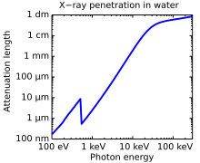
The linear attenuation coefficient, attenuation coefficient, or narrow-beam attenuation coefficient characterizes how easily a volume of material can be penetrated by a beam of light, sound, particles, or other energy or matter. A coefficient value that is large represents a beam becoming 'attenuated' as it passes through a given medium, while a small value represents that the medium had little effect on loss. The SI unit of attenuation coefficient is the reciprocal metre (m−1). Extinction coefficient is another term for this quantity, often used in meteorology and climatology. Most commonly, the quantity measures the exponential decay of intensity, that is, the value of downward e-folding distance of the original intensity as the energy of the intensity passes through a unit thickness of material, so that an attenuation coefficient of 1 m−1 means that after passing through 1 metre, the radiation will be reduced by a factor of e, and for material with a coefficient of 2 m−1, it will be reduced twice by e, or e2. Other measures may use a different factor than e, such as the decadic attenuation coefficient below. The broad-beam attenuation coefficient counts forward-scattered radiation as transmitted rather than attenuated, and is more applicable to radiation shielding.
The Kapitza–Dirac effect is a quantum mechanical effect consisting of the diffraction of matter by a standing wave of light. The effect was first predicted as the diffraction of electrons from a standing wave of light by Paul Dirac and Pyotr Kapitsa in 1933. The effect relies on the wave–particle duality of matter as stated by the de Broglie hypothesis in 1924.
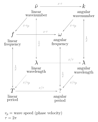
When an electromagnetic wave travels through a medium in which it gets attenuated, it undergoes exponential decay as described by the Beer–Lambert law. However, there are many possible ways to characterize the wave and how quickly it is attenuated. This article describes the mathematical relationships among:
Surface-extended X-ray absorption fine structure (SEXAFS) is the surface-sensitive equivalent of the EXAFS technique. This technique involves the illumination of the sample by high-intensity X-ray beams from a synchrotron and monitoring their photoabsorption by detecting in the intensity of Auger electrons as a function of the incident photon energy. Surface sensitivity is achieved by the interpretation of data depending on the intensity of the Auger electrons instead of looking at the relative absorption of the X-rays as in the parent method, EXAFS.

A substrate-integrated waveguide (SIW) is a synthetic rectangular electromagnetic waveguide formed in a dielectric substrate by densely arraying metallized posts or via holes that connect the upper and lower metal plates of the substrate. The waveguide can be easily fabricated with low-cost mass-production using through-hole techniques, where the post walls consists of via fences. SIW is known to have similar guided wave and mode characteristics to conventional rectangular waveguide with equivalent guide wavelength.
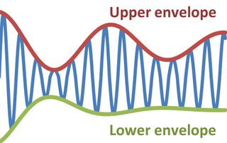
In physics and engineering, the envelope of an oscillating signal is a smooth curve outlining its extremes. The envelope thus generalizes the concept of a constant amplitude into an instantaneous amplitude. The figure illustrates a modulated sine wave varying between an upper envelope and a lower envelope. The envelope function may be a function of time, space, angle, or indeed of any variable.
Multidimensional seismic data processing forms a major component of seismic profiling, a technique used in geophysical exploration. The technique itself has various applications, including mapping ocean floors, determining the structure of sediments, mapping subsurface currents and hydrocarbon exploration. Since geophysical data obtained in such techniques is a function of both space and time, multidimensional signal processing techniques may be better suited for processing such data.
Stimulated Raman spectroscopy, also referred to as stimulated Raman scattering (SRS) is a form of spectroscopy employed in physics, chemistry, biology, and other fields. The basic mechanism resembles that of spontaneous Raman spectroscopy: a pump photon, of the angular frequency , which is scattered by a molecule has some small probability of inducing some vibrational transition, as opposed to inducing a simple Rayleigh transition. This makes the molecule emit a photon at a shifted frequency. However, SRS, as opposed to spontaneous Raman spectroscopy, is a third-order non-linear phenomenon involving a second photon—the Stokes photon of angular frequency —which stimulates a specific transition. When the difference in frequency between both photons resembles that of a specific vibrational transition the occurrence of this transition is resonantly enhanced. In SRS, the signal is equivalent to changes in the intensity of the pump and Stokes beams. The signals are typically rather low, of the order of a part in 10^5, thus calling for modulation-transfer techniques: one beam is modulated in amplitude and the signal is detected on the other beam via a lock-in amplifier. Employing a pump laser beam of a constant frequency and a Stokes laser beam of a scanned frequency allows for the unraveling of the spectral fingerprint of the molecule. This spectral fingerprint differs from those obtained by other spectroscopy methods such as Rayleigh scattering as the Raman transitions confer to different exclusion rules than those that apply for Rayleigh transitions.
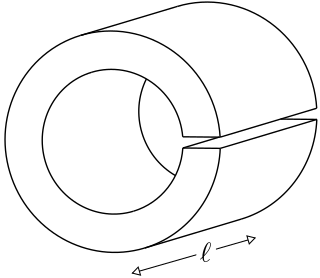
A loop-gap resonator (LGR) is an electromagnetic resonator that operates in the radio and microwave frequency ranges. The simplest LGRs are made from a conducting tube with a narrow slit cut along its length. The LGR dimensions are typically much smaller than the free-space wavelength of the electromagnetic fields at the resonant frequency. Therefore, relatively compact LGRs can be designed to operate at frequencies that are too low to be accessed using, for example, cavity resonators. These structures can have very sharp resonances making them useful for electron spin resonance (ESR) experiments, and precision measurements of electromagnetic material properties.