A plotting board was a mechanical device used by the U.S. Army Coast Artillery Corps as part of their fire control system to track the observed course of a target (typically a moving ship), project its future position, and derive the uncorrected data[note 1] on azimuth (or direction) and range needed to direct the fire of the guns of a battery to hit that target. Plotting boards of this sort were first employed by the Coast Artillery[note 2] around 1905, and were the primary means of calculating firing data until WW2. Towards the end of WW2 these boards were largely replaced by radar and electro-mechanical gun data computers, and were relegated to a back-up role.
Although several different types of plotting boards were used by the Coast Artillery over the years, the example described here is the Whistler-Hearn Plotting Board, Model of 1904 which was widely employed by the Coast Artillery between about 1905 and 1925.[note 3][1] This description is primarily derived from two manuals of the period, each of which leaves certain aspects of the board's design and use unexplained.[2][3] A 1940 manual also describes the Whistler-Hearn board.[4]
Overview
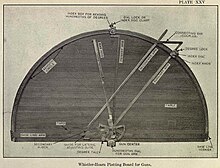
The Whistler-Hearn plotting board (see Plate XXV at right, top) was a semicircular wooden table about 7.5 feet in diameter with a mechanism on top that could be configured to represent the geography of the harbor area in which it was used, including the locations of the base end stations that observed targets for the gun battery it controlled and the location of the gun(s) of that battery. The guns were located with reference to their directing point, the point for which the firing data were calculated. Making the firing data relative to the position(s) of the gun(s) was called the relocation of these data. Relocation was part of the analog function of the plotting board and was enabled by adjustments to the gun arm center of the board (see plate and explanation below).
Photo of plotting board table topRelation between plotting board and the actual geography of the harbor
The mechanism of radial arms and adjustable slides, arcs, and gears converted observations that had been telephoned in from the base end stations into firing data for the guns.
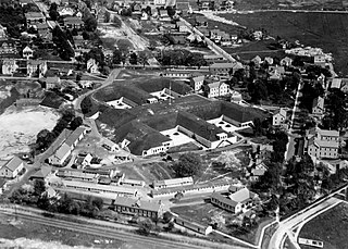
Plotting room, with Whistler-Hearn board
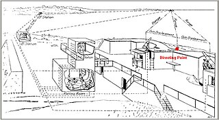
The plotting board for a given gun battery was located in the plotting room for that battery (shown at right, bottom), a space often attached to an observation post or protected within a reinforced concrete bunker or casemate. It was served by a large crew (often more than a dozen soldiers) who were part of the Range Section of the battery personnel.[6]
To locate a target, plotting board operators used two radial arms (called the primary and auxiliary arms), and "locked-in" the ends of these arms along on the notched azimuth scale that ran around the circumference of the board at the azimuths of the sightings that were telephoned in to them by the two base end stations. These locked arms and the baseline arm (along the base of the arc) then formed a triangle whose vertices were the two observation stations and the target. This located the target on the board,[note 4] and its position was then marked by punching a hole in the paper placed over the plotting board. Next, another radial arm, called the gun arm, was swung over the plotted position of the target, and the resulting range and azimuth for firing were read off the gun arm and an azimuth scale on the gun arm center. These data were corrected or adjusted for some other variables, and telephoned to the gun(s).[6]
The figure at left shows the actual relationship between the distant target (at top), the two base end stations (at either end of the baseline), and the directing point of the battery's guns, as reflected onto the plotting board. The triangle formed by the B1 (primary) arm, the B2 (secondary) arm and the base line arm is the small triangle at the base of the plotting board, and the gun arm is shown swung over the intersection of the other two arms in order to read the range and azimuth to the target. Another helpful diagram is shown on the base end station page—the cutaway diagram of a battery's plotting room (with its plotting board), shown next to the two base end stations, and behind the directing point of the battery, between its two guns.[6]
Customizing the plotting board to its site
Before it was used, a Whistler-Hearn board had to be set up and customized to the geography of the area at which it was to be used and for the location of the guns in the battery it was to direct.
First, the primary block (representing the primary base end station) was slid onto the bronze base-line arm (that extended all the way across the bottom diameter of the table) and secured at the exact center of that arm. Then, the secondary block (representing the secondary base end station) was slid onto the left or right end of the base-line arm (depending on the layout of the site) and set at a distance from the primary block that was equal to the (scaled) length of the base line at that site.[note 5][2]
Both the primary and the secondary block had a pintle, or pin, attached to it which represented (on the board) the surveyed position of the observing instrument in the primary or secondary base end station.[2]
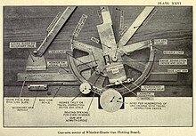
The secondary arm was installed on the pintle of the secondary block. On the pintle of the primary block were installed the primary arm, the auxiliary arm,[note 6] and the gun arm, as well as the complex gun arm center mechanism that was used to adjust the board for the location of the guns' directing point, to read the azimuth to the target, to adjust the firing data, and to tally the motion of the target between successive plotted positions. Plate XXVI (below, at right) shows a close-up of the gun arm center mechanism.[2]
The arc of the board was notched at one-degree intervals. To identify these notches with actual degrees of azimuth for a particular site, a zinc strip, with numbers of degrees of azimuth inscribed on it, was slipped into a slot on the surface of the board, towards its outer edge. The azimuth indicated by left edge of the base line arm was arbitrarily determined to be whatever azimuth fit the site, and adjusting screws with a vernier scale allowed for up to 0.5 degrees of "tweaking" of the base line arm's orientation.[3]
Next, two index boxes were slid onto the notched circumference edge of the board and the ends of the primary and auxiliary arms were inserted into these boxes. These boxes could be locked in position at whole-degree intervals (their teeth engaged the azimuth notches around the board), and each index box had a geared dial on its surface (with 100 teeth) that could be turned through one hundred parts of a degree, enabling each arm to be adjusted to within .01 degree of azimuth.[3]
Next, the gun arm center mechanism was slid from side to side and/or up and down with relation to the base line arm to account for the location of the battery's directing point to one side or the other of the primary base end station or behind or in front of the base line. These adjustments resulted in relocating (relating) the firing data sent to the guns to the actual (surveyed and calculated) positions of these guns. A further adjustment might need to be made by the gun crew to account for the distance of an individual gun from the battery's directing point, called its displacement.[3]
After these adjustments, the plotting board represented a true analog of the harbor being defended (see figure at left above) and was ready for use in fire control.
This customization of the board to its site, however, was also a weakness. It meant that the battery's fire control system was limited to using only the one baseline and only the two base end stations associated with that baseline.[note 7] If one of the two base end stations was put out of action (due to enemy fire or a communications casualty) the battery would have to switch to a less precise method of fire control, such as vertical base observation (using a depression position finder), the use of a self-contained rangefinder instrument, or aiming its guns directly, using their own telescopic sights.[note 8][3]
Using the plotting board
Using the plotting board required a team of five or six soldiers to handle the board itself, five or six more to handle equipment used to correct and adjust the resulting target coordinates[note 9] and a minimum of four more in the two distant base end stations. Many of the plotting board functions described below were performed repeatedly, during several successive observation/firing intervals (see Figure 1 below, left) that were indicated throughout the harbor defense system by the ringing of time interval bells.[3]
A series of observed positions (blue circles) established the likely track of the target. Using the plotting board, the set forward point was determined, based upon the target's observed course and speed and an assumption about when the gun was to be fired.
The process began when a target (e.g., an enemy ship) was identified by the harbor command and assigned to a given gun battery.[note 10] Observers in the two widely separated base end stations for the chosen battery tracked the target, using either azimuth scopes or more sophisticated depression position finders (DPFs). Azimuth scopes were only capable of locating the target in azimuth (bearing), while a DPF could be used for azimuth readings alone or could also measure the range from the base end station to the target.[3]
At the signal from the time interval bell, the reader in each base end station would read the azimuth of the target off of the instrument (to hundredths of a degree) and (using a headset phone) call this reading to the arm setter covering that station at the plotting board. Each of the two arm setters at the board moved his assigned arm (the primary or auxiliary arm) to the position on the notched azimuth scale (which ran around the circumference of the board) that corresponded to the azimuth reading (in whole degrees) he had just received by phone from his base end station. The arm setter then locked his arm at that position, using the index disk clamp at the end of the arm. Hundredths of a degree were indicated by turning the geared index disk, a wheel with 100 teeth that enabled adjusting the angle of the arm very precisely.[3]
With both arms set, a small block called the targ was slid up to the intersection of the arms and a mark was made on the plotting paper at the target's indicated position.[3]
This process of observing, setting the arms on the plotting board, and marking the target's position at the arms' intersection was repeated at the end of each observing interval for the battery. Since the firing of the gun(s) often occurred when the interval bell rang, the interval was also called a firing interval. The interval was usually set at 20 seconds.[note 11] After tracking a target for a short time, there would a string of plotted positions indicated on the board (e.g., the blue circles shown in Figure 1 above, left). This would then be sufficient for the plotting room to "connect the dots" with a projected course line (the black line in Figure 1) and estimate the target's speed.[3]
Next, a slide rule-like device called a set forward rule was used to mark off the set forward point (the green square in Figure 1) for the target. The set forward point was the anticipated position of the target at the end of the dead time plus the time of flight (see Figure 1).[note 12] The speed of the target was calculated from the time it took to cover the distances between the previously plotted points on its track. This type of fire control in the Coast Artillery was based upon the assumptions that the target steered in straight line and did not alter its speed during the 20-second (or longer) observing interval (or multiple intervals).[3]
Close-up of the mechanisms of the gun arm center, attached to the primary block of the plotting board
It was the set forward point that the guns were targeted to hit. This was accomplished by bringing the gun arm of the plotting board over this point, and reading the range from the directing point to the target off the range scale on the edge of that arm and the azimuth from the directing point to the target off of azimuth circle of the gun arm center. To see how this and further steps in the fire control process were accomplished, our attention shifts to the mechanisms of the gun arm center, shown in Plate XXVI at the right.[2]
Plate XXVI shows the gun arm (although the range scale on its edge is not visible), which points here toward the top of the photo (in the 11:30 position). It also shows the window (labeled at bottom center) through which the azimuth of the gun arm was read. Many of the other features of the gun arm center were used in correcting the firing data.[2]
Corrections in range were applied by turning the knob attached to a gear wheel (labeled "pinion" in Plate XXVI) at the center of the correction box, which slid the gun arm towards its circumference or back, with the adjustments indicated by index numbers visible through the window to the left of the pinion. Corrections in azimuth were achieved by turning the knurled knob at the right edge of the worm gear located at the bottom of the gun arm, with its pointer being used to read off index numbers and turn the gun arm through its arc.[2]
The dials on the face of the gun arm center were used to calculate the angular travel (in degrees and hundredths) of the target between successive plotted points on the board, a quantity that could be corrected (using output from a deflection board) and then applied to calculating the set forward point.[2]
↑ Before firing, the uncorrected firing data from the plotting board were corrected to account for such factors as the current weather, the level of the tide, the batch of powder being used by the guns, and/or were adjusted based on observations from spotters who reported on the fall of earlier shots at the same target. For details, see corrected firing data.
↑ Other types of plotting boards, used for the field artillery, are not described here.
↑ Other boards included the Cloke plotting and relocating board and the so-called 110 Degree plotting board.
↑ The target was not located by direct triangulation from the observations of the base end stations, even though the locations of these stations and the distance between them as well as their observing angles to the target were known. Rather it was the plotted position, relative to these stations and the DP, that was computed on the board.
↑ The usual scale for this type of plotting board was 300 yards to the inch, and the secondary station could be located on the baseline arm to the nearest scaled yard. If the secondary block was placed on the left-hand side of the primary block (as the user looked toward the arced edge of the board), the board was called "left-handed" (like the boards shown in all three images above).
↑ The offset between the secondary arm and the auxiliary arm was maintained by a connecting bar, which precisely represented (at the scale of the board) the length of the base line between the two base end stations.
↑ It was possible to reconfigure a Whistler-Hearn plotting board (by changing out the zinc strip around its circumference that held the actual azimuth values), by resetting the primary and secondary blocks on base line arm, and by readjusting the location of the gun arm center mechanism, but these adjustments were probably too complicated and time-consuming to be carried out during a battle.
↑ Plotting boards developed in the 1920s (like the Cloke board) could more easily be adapted to various baselines in the harbor area and have their base end stations reconfigured more quickly on the board.
↑ Ancillary plotting board equipment could include the range correction board, deviation correction board, spotting board, percentage corrector, and/or fire adjustment board.
↑ The target might have been first discovered by the observers in one of the chosen battery's base end stations, or it might have first been observed by another station. Large harbors often had a network of 20 to 30 base end stations covering all approaches to the harbor with an extensive network of telephone lines linking these stations, the harbor command, and the gun batteries.
↑ A very skilled battery (Range Section and gun crew) could handle an observing interval of 15 seconds, while a poorly trained battery might have trouble in following a 30 second interval schedule. Batteries drilled intensively to make their interval shorter, thus increasing their chances of putting more shots on the target per unit of time.
↑ The dead time was the time between the time that the observations upon which the firing data were based had been taken and the time the guns were fired. The time of flight was just that--the time it took the projectile to reach the target after it was fired.
Related Research Articles
Artillery is a class of heavy military ranged weapons that launch munitions far beyond the range and power of infantry firearms. Early artillery development focused on the ability to breach defensive walls and fortifications during sieges, and led to heavy, fairly immobile siege engines. As technology improved, lighter, more mobile field artillery cannons developed for battlefield use. This development continues today; modern self-propelled artillery vehicles are highly mobile weapons of great versatility generally providing the largest share of an army's total firepower.
Indirect fire is aiming and firing a projectile without relying on a direct line of sight between the gun and its target, as in the case of direct fire. Aiming is performed by calculating azimuth and inclination, and may include correcting aim by observing the fall of shot and calculating new angles.
In military organizations, an artillery battery is a unit or multiple systems of artillery, mortar systems, rocket artillery, multiple rocket launchers, surface-to-surface missiles, ballistic missiles, cruise missiles, etc., so grouped to facilitate better battlefield communication and command and control, as well as to provide dispersion for its constituent gunnery crews and their systems. The term is also used in a naval context to describe groups of guns on warships.
An artillery observer,artillery spotter, or forward observer (FO) is a soldier responsible for directing artillery and mortar fire support onto a target. An artillery observer usually accompanies a tank or infantry unit. Spotters ensure that indirect fire hits targets which those at a fire support base cannot see.
A fire-control system (FCS) is a number of components working together, usually a gun data computer, a director and radar, which is designed to assist a ranged weapon system to target, track, and hit a target. It performs the same task as a human gunner firing a weapon, but attempts to do so faster and more accurately.
Counter-battery fire is a battlefield tactic employed to defeat the enemy's indirect fire elements, including their target acquisition, as well as their command and control components. Counter-battery arrangements and responsibilities vary between nations but involve target acquisition, planning and control, and counter-fire. Counter-battery fire rose to prominence in World War I.
Field artillery is a category of mobile artillery used to support armies in the field. These weapons are specialized for mobility, tactical proficiency, short range, long range, and extremely long range target engagement.
Gun laying is the process of aiming an artillery piece or turret, such as a gun, howitzer, or mortar, on land, in air, or at sea, against surface or aerial targets. It may be laying for direct fire, where the gun is aimed similarly to a rifle, or indirect fire, where firing data is calculated and applied to the sights. The term includes automated aiming using, for example, radar-derived target data and computer-controlled guns.
Base end stations were used by the United States Army Coast Artillery Corps as part of fire control systems for locating the positions of attacking ships and controlling the firing of seacoast guns, mortars, or mines to defend against them. A British equivalent was the position finding cell.
A fire control tower is a structure located near the coastline, used to detect and locate enemy vessels offshore, direct fire upon them from coastal batteries, or adjust the aim of guns by spotting shell splashes. Fire control towers came into general use in coastal defence systems in the late 19th century, as rapid development significantly increased the range of both naval guns and coastal artillery. This made fire control more complex. These towers were used in a number of countries' coastal defence systems through 1945, much later in a few cases such as Sweden. The Atlantic Wall in German-occupied Europe during World War II included fire control towers.
A director, also called an auxiliary predictor, is a mechanical or electronic computer that continuously calculates trigonometric firing solutions for use against a moving target, and transmits targeting data to direct the weapon firing crew.
A plotting room was the co-ordination centre of a fire control system for guns used against enemy ships or aircraft, whether naval guns or coastal artillery. The plotting room received data on ship or aircraft position and motion from fire control instruments or their operators and determined and transmitted the range and bearing the guns would fire on. Plotting rooms came into use in the early 1900s for coastal artillery and during World War I for warships as gun ranges increased, and were in general use through the 1970s on World War II-era ships. Warships had plotting rooms for naval fire control for guns from 5-inch to 18-inch calibre, including anti-aircraft use for the smaller guns. On armoured ships such as battleships and cruisers, plotting rooms were located in the armoured citadel, protected by both deck and belt armour. With a few exceptions, coastal defence gun installations were inactivated shortly after World War II (US) through the middle 1950s (UK). Equipment in plotting rooms included specialised plotting boards and other analogue devices; by World War II these were supplemented or replaced by electro-mechanical gun data computers. Data could be received and transmitted by telephone, or directly via dedicated electrical systems. Locations of plotting rooms in coastal defence installations varied greatly; they could be in low-rise structures such as base end stations, taller fire control towers, in gun battery structures, or in bunkers separate from gun batteries.
In the U.S. Army Coast Artillery Corps, the term fire control system was used to refer to the personnel, facilities, technology and procedures that were used to observe designated targets, estimate their positions, calculate firing data for guns directed to hit those targets, and assess the effectiveness of such fire, making corrections where necessary.
The directing point (DP) was a term used in the United States Army Coast Artillery Corps to identify a precisely surveyed point that was used as the point of reference for preparing the firing data used to aim the guns of a given Coast Artillery battery.
Fort Banks was a U.S. Coast Artillery fort located in Winthrop, Massachusetts. It served to defend Boston Harbor from enemy attack from the sea and was built in the 1809 during what is known as the Endicott period, a time in which the coast defenses of the United States were seriously expanded and upgraded with new technology. Today, the fort's mortar battery is on the National Register of Historic Places.
The 14-inch M1920 railway gun was the last model railway gun to be deployed by the United States Army. It was an upgrade of the US Navy 14"/50 caliber railway gun. Only four were deployed; two in the Harbor Defenses of Los Angeles and two in the Panama Canal Zone, where they could be shifted between the harbor defenses of Cristobal (Atlantic) or Balboa (Pacific).
The 12-inch coast defense mortar was a weapon of 12-inch (305 mm) caliber emplaced during the 1890s and early 20th century to defend US harbors from seaborne attack. In 1886, when the Endicott Board set forth its initial plan for upgrading the coast defenses of the United States, it relied primarily on mortars, not guns, to defend American harbors. Over the years, provision was made for fortifications that would mount some 476 of these weapons, although not all of these tubes were installed. Ninety-one of these weapons were remounted as railway artillery in 1918-1919, but this was too late to see action in World War I. The railway mortars were only deployed in small quantities, and none overseas. The fixed mortars in the Philippines saw action in the Japanese invasion in World War II. All of the fixed mortars in the United States were scrapped by 1944, as new weapons replaced them, and the railway mortars were scrapped after the war. Today, the only remaining mortars of this type in the 50 states are four at Battery Laidley, part of Fort Desoto near St. Petersburg, Florida, but the remains of coast defense mortar emplacements can be seen at many former Coast Artillery forts across the United States and its former territories. Additional 12-inch mortars and other large-caliber weapons remain in the Philippines.
The Harbor Defenses of Portsmouth was a United States Army Coast Artillery Corps harbor defense command. It coordinated the coast defenses of Portsmouth, New Hampshire and the nearby Portsmouth Naval Shipyard in Kittery, Maine from 1900 to 1950, both on the Piscataqua River, beginning with the Endicott program. These included both coast artillery forts and underwater minefields. The command originated circa 1900 as the Portsmouth Artillery District, was renamed Coast Defenses of Portsmouth in 1913, and again renamed Harbor Defenses of Portsmouth in 1925.
The depression range finder (DRF) was a fire control device used to determine the target's position by observing range and bearing and to calculate firing solutions when gun laying in coastal artillery. It was the main component of a vertical base rangefinding system. It was necessitated by the introduction of rifled artillery from the mid-19th century onwards, which had much greater ranges than the old smoothbore weapons and were consequently more difficult to aim accurately. The DRF was invented by Captain H.S.S. Watkin of the Royal Artillery in the 1870s and was adopted in 1881. It could provide both range and bearing information on a target. The device's inventor also developed a family of similar devices, among them the position finder, which used two telescopes as a horizontal base rangefinding system, around the same time; some of these were called electric position finders. Some position finders retained a depression range finding capability; some of these were called depression position finders. Watkin's family of devices were deployed in position finding cells, a type of fire control tower, often in configurations that allowed both horizontal base and vertical base rangefinding. Watkin's system included automatic electrical updating of range and bearing dials near the guns as the position finders were manipulated, and a system of remotely firing the guns electrically from the position finding cell. The improved system was trialled in 1885 and widely deployed in the 1890s. Functionally equivalent devices were developed for the United States Army Coast Artillery Corps and its predecessors, called depression position finders or azimuth instruments depending on function, adopted in 1896 and deployed widely beginning in the early 1900s as the Endicott program of modern coastal defences was built. These devices were also used by both countries to control submarine (underwater) minefields.
1 2 3 4 5 6 7 8 9 10 11 "Training Manual No. 1669: Description of the Whistler-Hearn Plotting Board (Model of 1904), Mortar Plotting Board (Model of 1906 and Model of 1906 MI), and Submarine Plotting Board (Model of 1906) and Instructions for Assembling, Adjusting, Caring the, Etc.," Ordnance Department, U.S. Army, Government Printing Office, Washington, April 24, 1907, Revised December 13, 1909.
This page is based on this Wikipedia article Text is available under the CC BY-SA 4.0 license; additional terms may apply. Images, videos and audio are available under their respective licenses.