Ring counter

Last updated

A ring counter is a type of counter composed of flip-flops connected into a shift register, with the output of the last flip-flop fed to the input of the first, making a "circular" or "ring" structure.

Contents

There are two types of ring counters:

Four-bit ring-counter sequences

Straight ring counterJohnson counter
StateQ0Q1Q2Q3StateQ0Q1Q2Q3
01000 00000
10100 11000
20010 21100
30001 31110
01000 41111
10100 50111
20010 60011
30001 70001
01000 00000

Properties

Ring counters are often used in hardware design (e.g. ASIC and FPGA design) to create finite-state machines. A binary counter would require an adder circuit which is substantially more complex than a ring counter and has higher propagation delay as the number of bits increases, whereas the propagation delay of a ring counter will be nearly constant regardless of the number of bits in the code.

The straight and twisted forms have different properties, and relative advantages and disadvantages.

A general disadvantage of ring counters is that they are lower density codes than normal binary encodings of state numbers. A binary counter can represent 2N states, where N is the number of bits in the code, whereas a straight ring counter can represent only N states and a Johnson counter can represent only 2N states. This may be an important consideration in hardware implementations where registers are more expensive than combinational logic.

Johnson counters are sometimes favored, because they offer twice as many count states from the same number of shift registers, and because they are able to self-initialize from the all-zeros state, without requiring the first count bit to be injected externally at start-up. The Johnson counter generates a code in which adjacent states differ by only one bit (that is, have a Hamming distance of 1), as in a Gray code, which can be useful if the bit pattern is going to be asynchronously sampled. [1]

When a fully decoded or one-hot representation of the counter state is needed, as in some sequence controllers, the straight ring counter is preferred. The one-hot property means that the set of codes are separated by a minimum Hamming distance of 2, [2] so any single-bit error is detectable (as is any error pattern other than turning on one bit and turning off one bit).

Sometimes bidirectional shift registers are used (using multiplexors to take the input for each flip-flop from its left or right neighbor), so that bidirectional or up–down ring counters can be made. [3]

Logic diagrams

The straight ring counter has the logical structure shown here:

Overbeck Counter 4bit.svg

Instead of the reset line setting up the initial one-hot pattern, the straight ring is sometimes made self-initializing by the use of a distributed feedback gate across all of the outputs except that last, so that a 1 is presented at the input when there is no 1 in any stage but the last. [4]

A Johnson counter, named for Robert Royce Johnson, is a ring with an inversion; here is a 4-bit Johnson counter:

Johnson Counter 4bit.svg

Note the small bubble indicating inversion of the Q signal from the last shift register before feeding back to the first D input, making this a Johnson counter.

History

Before the days of digital computing, digital counters were used to measure rates of random events such as radioactive decays to alpha and beta particle. Fast "pre-scaling" counters reduced the rate of random events to more manageable and more regular rates. Five-state ring counters were used along with divide-by-two scalers to make decade (power-of-ten) scalers before 1940, such as those developed by C. E. Wynn-Williams. [5]

Early ring counters used only one active element (vacuum tube, valve, or transistor) per stage, relying on global feedback rather than local bistable flip-flops, to suppress states other than the one-hot states, for example in the 1941 patent filing of Robert E. Mumma of the National Cash Registor Company. [6] Wilcox P. Overbeck invented a version using multiple anodes in a single vacuum tube, [7] [8] In recognition of his work, ring counters are sometimes referred to as "Overbeck rings" [9] [10] (and after 2006, sometimes as "Overbeck counters", since Wikipedia used that term from 2006 to 2018).

The ENIAC used decimal arithmetic based on 10-state one-hot ring counters. The works of Mumma at NCR and Overbeck at MIT were among the prior art works examined by the patent office in invalidated the patents of J. Presper Eckert and John Mauchly for the ENIAC technology. [11]

By the 1950s, ring counters with a two-tube or twin-triode flip-flop per stage were appearing. [12]

Robert Royce Johnson developed a number of different shift-register-based counters with the aim of making different numbers of states with the simplest possible feedback logic, and filed for a patent in 1953. [13] The Johnson counter is the simplest of these.

Applications

Early applications of ring counters were as frequency prescalers (e.g. for Geiger counter and such instruments), [5] as counters to count pattern occurrences in cryptanalysis (e.g. in the Heath Robinson codebreaking machine and the Colossus computer), [14] and as accumulator counter elements for decimal arithmetic in computers and calculators, using either bi-quinary (as in the Colossus) or ten-state one-hot (as in the ENIAC) representations.

Straight ring counters generate fully decoded one-hot codes to that are often used to enable a specific action in each state of a cyclic control cycle. One-hot codes can also be decoded from a Johnson counter, using one gate for each state. [15] [nb 1]

Besides being an efficient alternative way to generate one-hot codes and frequency pre-scalers, a Johnson counter is also a simple way to encode a cycle of an even number of states that can be asynchronously sampled without glitching, since only one bit changes at a time, as in a Gray code. [16] Early computer mice used up–down (bidirectional) 2-bit Johnson or Gray encodings to indicate motion in each of the two dimensions, though in mice those codes were not usually generated by rings of flip-flops (but instead by electro-mechanical or optical quadrature encoders). [17] A 2-bit Johnson code and a 2-bit Gray code are identical, while for 3 or more bits Gray and Johnson codes are different. In the 5-bit case, the code is the same as the Libaw–Craig code  [ de ] for decimal digits. [18] [19] [20] [21] [22] [23] [24] [25]

A walking ring counter, also called a Johnson counter, and a few resistors can produce a glitch-free approximation of a sine wave. When combined with an adjustable prescaler, this is perhaps the simplest numerically-controlled oscillator. Two such walking ring counters are perhaps the simplest way to generate the continuous-phase frequency-shift keying used in dual-tone multi-frequency signaling and early modem tones. [26]

Decimal
 
0
1
2
3
4
5
6
7
8
9
1-bit
1
0
1
0
1
0
1
0
1
0
1
2-bit
21
00
01
11
10
00
01
11
10
00
01
3-bit
321
000
001
011
111
110
100
000
001
011
111
4-bit Johnson
4321
0000
0001
0011
0111
1111
1110
1100
1000
0000
0001
Libaw–Craig
54321
00000
00001
00011
00111
01111
11111
11110
11100
11000
10000
1-2-1
54321
10001
00001
00011
00010
00110
00100
01100
01000
11000
10000
1-of-10
10987654321
0000000001
0000000010
0000000100
0000001000
0000010000
0000100000
0001000000
0010000000
0100000000
1000000000

See also

Notes

  1. Johnson counter circuits with single states decoded in this way can be found in the original IBM MDA and CGA video display adapter designs, in the timing sequencer logic: one or two 74x174 hex D-type flip-flop ICs are wired as a shift register, fed back with inversion to form a Johnson counter, and 2-input NAND gates (in the MDA) or XOR gates (in the CGA) are used to decode states used as signals such as +RAS (Row Address Strobe [to DRAM]) and S/-L (Shift / NOT Load). Source: IBM Personal Computer Options & Adapters Technical Reference, Monochrome Display and Printer Adapter, logic diagrams; IBM Personal Computer Options & Adapters Technical Reference, Color Graphics Monitor Adapter, logic diagrams.

Related Research Articles

In digital logic and computing, a counter is a device which stores the number of times a particular event or process has occurred, often in relationship to a clock. The most common type is a sequential digital logic circuit with an input line called the clock and multiple output lines. The values on the output lines represent a number in the binary or BCD number system. Each pulse applied to the clock input increments or decrements the number in the counter.

In processor design, microcode serves as an intermediary layer situated between the central processing unit (CPU) hardware and the programmer-visible instruction set architecture of a computer, also known as its machine code. It consists of a set of hardware-level instructions that implement the higher-level machine code instructions or control internal finite-state machine sequencing in many digital processing components. While microcode is utilized in general-purpose CPUs in contemporary desktops, it also functions as a fallback path for scenarios that the faster hardwired control unit is unable to manage.

<span class="mw-page-title-main">Digital electronics</span> Electronic circuits that utilize digital signals

Digital electronics is a field of electronics involving the study of digital signals and the engineering of devices that use or produce them. This is in contrast to analog electronics and analog signals.

A shift register is a type of digital circuit using a cascade of flip-flops where the output of one flip-flop is connected to the input of the next. They share a single clock signal, which causes the data stored in the system to shift from one location to the next. By connecting the last flip-flop back to the first, the data can cycle within the shifters for extended periods, and in this configuration they were used as computer memory, displacing delay-line memory systems in the late 1960s and early 1970s.

The reflected binary code (RBC), also known as reflected binary (RB) or Gray code after Frank Gray, is an ordering of the binary numeral system such that two successive values differ in only one bit.

In computing, a linear-feedback shift register (LFSR) is a shift register whose input bit is a linear function of its previous state.

<span class="mw-page-title-main">Programmable logic device</span> Reconfigurable digital circuit element

A programmable logic device (PLD) is an electronic component used to build reconfigurable digital circuits. Unlike digital logic constructed using discrete logic gates with fixed functions, a PLD has an undefined function at the time of manufacture. Before the PLD can be used in a circuit it must be programmed to implement the desired function. Compared to fixed logic devices, programmable logic devices simplify the design of complex logic and may offer superior performance. Unlike for microprocessors, programming a PLD changes the connections made between the gates in the device.

<span class="mw-page-title-main">IBM 1620</span> Small IBM scientific computer released in 1959

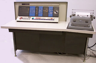
The IBM 1620 was announced by IBM on October 21, 1959, and marketed as an inexpensive scientific computer. After a total production of about two thousand machines, it was withdrawn on November 19, 1970. Modified versions of the 1620 were used as the CPU of the IBM 1710 and IBM 1720 Industrial Process Control Systems.

<span class="mw-page-title-main">Emitter-coupled logic</span>

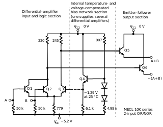
In electronics, emitter-coupled logic (ECL) is a high-speed integrated circuit bipolar transistor logic family. ECL uses an overdriven bipolar junction transistor (BJT) differential amplifier with single-ended input and limited emitter current to avoid the saturated region of operation and its slow turn-off behavior. As the current is steered between two legs of an emitter-coupled pair, ECL is sometimes called current-steering logic (CSL), current-mode logic (CML) or current-switch emitter-follower (CSEF) logic.

<span class="mw-page-title-main">4000-series integrated circuits</span> Series of CMOS logic integrated circuits

The 4000 series is a CMOS logic family of integrated circuits (ICs) first introduced in 1968 by RCA. It was slowly migrated into the 4000B buffered series after about 1975. It had a much wider supply voltage range than any contemporary logic family. Almost all IC manufacturers active during this initial era fabricated models for this series. Its naming convention is still in use today.

In digital electronics, a binary decoder is a combinational logic circuit that converts binary information from the n coded inputs to a maximum of 2n unique outputs. They are used in a wide variety of applications, including instruction decoding, data multiplexing and data demultiplexing, seven segment displays, and as address decoders for memory and port-mapped I/O.

In the history of computer hardware, some early reduced instruction set computer central processing units used a very similar architectural solution, now called a classic RISC pipeline. Those CPUs were: MIPS, SPARC, Motorola 88000, and later the notional CPU DLX invented for education.

Excess-3, 3-excess or 10-excess-3 binary code, shifted binary or Stibitz code is a self-complementary binary-coded decimal (BCD) code and numeral system. It is a biased representation. Excess-3 code was used on some older computers as well as in cash registers and hand-held portable electronic calculators of the 1970s, among other uses.

<span class="mw-page-title-main">MOS Technology 6522</span> Microprocessor I/O port controller IC

The MOS Technology 6522 Versatile Interface Adapter (VIA) is an integrated circuit that was designed and manufactured by MOS Technology as an I/O port controller for the 6502 family of microprocessors. It provides two bidirectional 8-bit parallel I/O ports, two 16-bit timers, and an 8-bit shift register for serial communications or data conversion between serial and parallel forms. The direction of each bit of the two I/O ports can be individually programmed. In addition to being manufactured by MOS Technology, the 6522 was second sourced by other companies including Rockwell and Synertek.

In digital circuits and machine learning, a one-hot is a group of bits among which the legal combinations of values are only those with a single high (1) bit and all the others low (0). A similar implementation in which all bits are '1' except one '0' is sometimes called one-cold. In statistics, dummy variables represent a similar technique for representing categorical data.

A frequency divider, also called a clock divider or scaler or prescaler, is a circuit that takes an input signal of a frequency, , and generates an output signal of a frequency:

<span class="mw-page-title-main">Flip-flop (electronics)</span> Electronic circuit with two stable states

In electronics, flip-flops and latches are circuits that have two stable states that can store state information – a bistable multivibrator. The circuit can be made to change state by signals applied to one or more control inputs and will output its state. It is the basic storage element in sequential logic. Flip-flops and latches are fundamental building blocks of digital electronics systems used in computers, communications, and many other types of systems.

<span class="mw-page-title-main">Memory cell (computing)</span> Part of computer memory

The memory cell is the fundamental building block of computer memory. The memory cell is an electronic circuit that stores one bit of binary information and it must be set to store a logic 1 and reset to store a logic 0. Its value is maintained/stored until it is changed by the set/reset process. The value in the memory cell can be accessed by reading it.

State encoding assigns a unique pattern of ones and zeros to each defined state of a finite-state machine (FSM). Traditionally, design criteria for FSM synthesis were speed, area or both. Following Moore's law, with technology advancement, density and speed of integrated circuits have increased exponentially. With this, power dissipation per area has inevitably increased, which has forced designers for portable computing devices and high-speed processors to consider power dissipation as a critical parameter during design consideration.

<span class="mw-page-title-main">Vacuum-tube computer</span> Earliest electronic computer design

A vacuum-tube computer, now termed a first-generation computer, is a computer that uses vacuum tubes for logic circuitry. While the history of mechanical aids to computation goes back centuries, if not millennia, the history of vacuum tube computers is confined to the middle of the 20th century. Lee De Forest invented the triode in 1906. The first example of using vacuum tubes for computation, the Atanasoff–Berry computer, was demonstrated in 1939. Vacuum-tube computers were initially one-of-a-kind designs, but commercial models were introduced in the 1950s and sold in volumes ranging from single digits to thousands of units. By the early 1960s vacuum tube computers were obsolete, superseded by second-generation transistorized computers.

References

  1. Pedroni, Volnei A. (2013). Finite State Machines in Hardware: Theory and Design. MIT Press. p. 50. ISBN   978-0-26201966-8.
  2. Mengibar, Luis; Entrena, Luis; Lorenz, Michael G.; Sánchez-Reillo, Raúl (2003). "State Encoding for Low-Power FSMs in FPGA". Integrated Circuit and System Design. Power and Timing Modeling, Optimization and Simulation: Proceedings of the 13th International Workshop, PATMOS 2003, Torino, Italy, 10–12 September 2003. Vol. 13. Springer Science & Business Media. p. 35. ISBN   9783540200741.
  3. Stan, Mircea R. (1997). "Synchronous up/down counter with clock period independent of counter size" (PDF). Proceedings 13th IEEE Symposium on Computer Arithmetic: 274–281.
  4. Holdsworth, Brian; Woods, Clive (2002). Digital Logic Design (4 ed.). Newnes Books / Elsevier Science. pp. 191–192. ISBN   0-7506-4588-2 . Retrieved 2020-04-19.{{cite book}}: CS1 maint: ignored ISBN errors (link) (519 pages)
  5. 1 2 Lewis, Wilfrid Bennett (1942). Electrical Counting: With Special Reference to Counting Alpha and Beta Particles. Cambridge University Press. p. 90. ISBN   9781316611760.
  6. "Electronic accumulation", Robert E. Mumma's US Patent No. 2405096, filed in 1941
  7. "Electronic switching device", Wilcox P. Overbeck's US Patent No. 2427533, filed in 1943
  8. Dayton Codebreakers: 1942 Research Report, mentioning "A new high speed counter by Mr. Overbeck, January 8, 1942"
  9. RAMAC 305 - IBM Customer Engineering Manual of Instruction (PDF). IBM. 1959. […] The Overbeck ring is used to supply timed pulses within computer circuits much as cam operated circuit breakers supply timed pulses on mechanical machines. It consists of a set of triggers with a common input from the ring drive line which carries pulses supplied by the process drum. […] Initially the triggers are reset OFF with the exception of the home trigger, which is ON. Each negative input pulse will turn OFF the trigger that is ON. The fall of the voltage at pin 10 of the trigger being turned OFF will grid flip the next trigger ON. This continues through a closed ring […]
  10. Electrical Technology - A Suggested 2-Year Post High School Curriculum. Technical Education Program Series. United States, Division of Vocational and Technical Education. 1960. p. 52.
  11. Randall, Brian (2014). "The Origins of Digital Computers: Supplementary Bibliography". In Metropolis, Nicholas (ed.). History of Computing in the Twentieth Century. Elsevier. pp. 651–652. ISBN   9781483296685.
  12. William Alfred Higinbotham, "Fast impulse circuits", US Patent No. 2536808, filed in 1949
  13. Robert Royce Johnson, "Electronic counter", US Patent No. 3030581, filed in 1953
  14. Copeland, B. Jack (2010). Colossus: The Secrets of Bletchley Park's Code-breaking Computers. Oxford University Press. pp. 123–128. ISBN   978-0-19957814-6.
  15. Langholz, Gideon; Kandel, Abraham; Mott, Joe L. (1998). Foundations of Digital Logic Design. World Scientific. pp. 525–526. ISBN   978-9-81023110-1.
  16. van Holten, Cornelius (August 1982). Written at Delft Technical University, Delft, Netherlands. "Digital dividers with symmetrical outputs - The author uses Johnson counters with controlled feedback to give symmetrical even and odd-numbered divisions of a clock pulse" (PDF). Wireless World . Vol. 88, no. 1559. Sutton, Surrey, UK: IPC Business Press Ltd. pp. 43–46. ISSN   0043-6062. Archived (PDF) from the original on 2021-02-21. Retrieved 2021-02-20. (4 pages)
  17. Lyon, Richard F. (August 1981), The Optical Mouse, and an Architectural Methodology for Smart Digital Sensors (PDF) (Report), Palo Alto Research Center, Palo Alto, California, USA: Xerox Corporation, VLSI 81-1, archived (PDF) from the original on 2020-05-23, retrieved 2020-05-23, The counters needed for X and Y simply count through four states, in either direction (up or down), changing only one bit at a time (i.e., 00, 01, 11, 10). This is a simple case of either a Gray-code counter or a Johnson counter (Moebius counter). (41 pages)
  18. Libaw, William H.; Craig, Leonard J. (October 1953) [September 1953]. "A Photoelectric Decimal-Coded Shaft Digitizer". Transactions of the I.R.E. Professional Group on Electronic Computers . EC-2 (3): 1–4. doi:10.1109/IREPGELC.1953.5407731. eISSN   2168-1759. ISSN   2168-1740 . Retrieved 2020-05-26. (4 pages)
  19. Powell, E. Alexander (June 1968). "Codes particularly useful for analogue to digital conversions". A short note on useful codes for Fluidic Control Circuits (PDF). Cranfield, UK: The College of Aeronautics, Department of Production Engineering. p. 10. S2CID   215864694. CoA Memo 156. Archived (PDF) from the original on 2020-12-15. Retrieved 2020-12-15. (18 pages) (NB. The paper names the Glixon code modified Gray code and misspells Richard W. Hamming's name.)
  20. Dokter, Folkert; Steinhauer, Jürgen (1973-06-18). Digital Electronics. Philips Technical Library (PTL) / Macmillan Education (Reprint of 1st English ed.). Eindhoven, Netherlands: The Macmillan Press Ltd. / N. V. Philips' Gloeilampenfabrieken. p. 43. doi:10.1007/978-1-349-01417-0. ISBN   978-1-349-01419-4. SBN   333-13360-9 . Retrieved 2020-05-11. (270 pages)
  21. Dokter, Folkert; Steinhauer, Jürgen (1975) [1969]. Digitale Elektronik in der Meßtechnik und Datenverarbeitung: Theoretische Grundlagen und Schaltungstechnik. Philips Fachbücher (in German). Vol. I (improved and extended 5th ed.). Hamburg, Germany: Deutsche Philips GmbH. pp. 52, 58, 98. ISBN   3-87145-272-6. (xii+327+3 pages)
  22. Dokter, Folkert; Steinhauer, Jürgen (1975) [1970]. Digitale Elektronik in der Meßtechnik und Datenverarbeitung: Anwendung der digitalen Grundschaltungen und Gerätetechnik. Philips Fachbücher (in German). Vol. II (4th ed.). Hamburg, Germany: Deutsche Philips GmbH. p. 169. ISBN   3-87145-273-4. (xi+393+3 pages)
  23. Steinbuch, Karl W., ed. (1962). Written at Karlsruhe, Germany. Taschenbuch der Nachrichtenverarbeitung (in German) (1 ed.). Berlin / Göttingen / New York: Springer-Verlag OHG. pp. 71–72, 74. LCCN   62-14511.
  24. Steinbuch, Karl W.; Wagner, Siegfried W., eds. (1967) [1962]. Taschenbuch der Nachrichtenverarbeitung (in German) (2 ed.). Berlin, Germany: Springer-Verlag OHG. LCCN   67-21079. Title No. 1036.
  25. Steinbuch, Karl W.; Weber, Wolfgang; Heinemann, Traute, eds. (1974) [1967]. Taschenbuch der Informatik – Band II – Struktur und Programmierung von EDV-Systemen (in German). Vol. 2 (3 ed.). Berlin, Germany: Springer Verlag. ISBN   3-540-06241-6. LCCN   73-80607.{{cite book}}: |work= ignored (help)
  26. Don Lancaster. "TV Typewriter Cookbook". (TV Typewriter). 1976. p. 180-181.