
An amplifier, electronic amplifier or (informally) amp is an electronic device that can increase the magnitude of a signal. It is a two-port electronic circuit that uses electric power from a power supply to increase the amplitude of a signal applied to its input terminals, producing a proportionally greater amplitude signal at its output. The amount of amplification provided by an amplifier is measured by its gain: the ratio of output voltage, current, or power to input. An amplifier is defined as a circuit that has a power gain greater than one.

In electronics, an analog-to-digital converter is a system that converts an analog signal, such as a sound picked up by a microphone or light entering a digital camera, into a digital signal. An ADC may also provide an isolated measurement such as an electronic device that converts an analog input voltage or current to a digital number representing the magnitude of the voltage or current. Typically the digital output is a two's complement binary number that is proportional to the input, but there are other possibilities.
In electronics, a digital-to-analog converter is a system that converts a digital signal into an analog signal. An analog-to-digital converter (ADC) performs the reverse function.

A preamplifier, also known as a preamp, is an electronic amplifier that converts a weak electrical signal into an output signal strong enough to be noise-tolerant and strong enough for further processing, or for sending to a power amplifier and a loudspeaker. Without this, the final signal would be noisy or distorted. They are typically used to amplify signals from analog sensors such as microphones and pickups. Because of this, the preamplifier is often placed close to the sensor to reduce the effects of noise and interference.

A voltage-controlled oscillator (VCO) is an electronic oscillator whose oscillation frequency is controlled by a voltage input. The applied input voltage determines the instantaneous oscillation frequency. Consequently, a VCO can be used for frequency modulation (FM) or phase modulation (PM) by applying a modulating signal to the control input. A VCO is also an integral part of a phase-locked loop. VCOs are used in synthesizers to generate a waveform whose pitch can be adjusted by a voltage determined by a musical keyboard or other input.

In electronics, a chopper circuit is any of numerous types of electronic switching devices and circuits used in power control and signal applications. A chopper is a device that converts fixed DC input to a variable DC output voltage directly. Essentially, a chopper is an electronic switch that is used to interrupt one signal under the control of another.

An electronic component is any basic discrete electronic device or physical entity part of an electronic system used to affect electrons or their associated fields. Electronic components are mostly industrial products, available in a singular form and are not to be confused with electrical elements, which are conceptual abstractions representing idealized electronic components and elements. A datasheet for an electronic component is a technical document that provides detailed information about the component's specifications, characteristics, and performance.
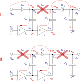
A charge pump is a kind of DC-to-DC converter that uses capacitors for energetic charge storage to raise or lower voltage. Charge-pump circuits are capable of high efficiencies, sometimes as high as 90–95%, while being electrically simple circuits.
The cascode is a two-stage amplifier that consists of a common-emitter stage feeding into a common-base stage.
This article illustrates some typical operational amplifier applications. A non-ideal operational amplifier's equivalent circuit has a finite input impedance, a non-zero output impedance, and a finite gain. A real op-amp has a number of non-ideal features as shown in the diagram, but here a simplified schematic notation is used, many details such as device selection and power supply connections are not shown. Operational amplifiers are optimised for use with negative feedback, and this article discusses only negative-feedback applications. When positive feedback is required, a comparator is usually more appropriate. See Comparator applications for further information.

A charge amplifier is an electronic current integrator that produces a voltage output proportional to the integrated value of the input current, or the total charge injected.
A switched capacitor (SC) is an electronic circuit that implements a function by moving charges into and out of capacitors when electronic switches are opened and closed. Usually, non-overlapping clock signals are used to control the switches, so that not all switches are closed simultaneously. Filters implemented with these elements are termed switched-capacitor filters, which depend only on the ratios between capacitances and the switching frequency, and not on precise resistors. This makes them much more suitable for use within integrated circuits, where accurately specified resistors and capacitors are not economical to construct, but accurate clocks and accurate relative ratios of capacitances are economical.
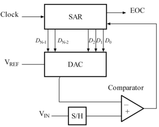
A successive-approximation ADC is a type of analog-to-digital converter that converts a continuous analog waveform into a discrete digital representation using a binary search through all possible quantization levels before finally converging upon a digital output for each conversion.
In the field of electronics, a technique where part of the output of a system is used at startup can be described as bootstrapping.

CircuitLogix is a software electronic circuit simulator which uses PSpice to simulate thousands of electronic devices, models, and circuits. CircuitLogix supports analog, digital, and mixed-signal circuits, and its SPICE simulation gives accurate real-world results. The graphic user interface allows students to quickly and easily draw, modify and combine analog and digital circuit diagrams. CircuitLogix was first launched in 2005, and its popularity has grown quickly since that time. In 2012, it reached the milestone of 250,000 licensed users, and became the first electronics simulation product to have a global installed base of a quarter-million customers in over 100 countries.

The current-feedback operational amplifier is a type of electronic amplifier whose inverting input is sensitive to current, rather than to voltage as in a conventional voltage-feedback operational amplifier (VFA). The CFA was invented by David Nelson at Comlinear Corporation, and first sold in 1982 as a hybrid amplifier, the CLC103. An early patent covering a CFA is U.S. Patent 4,502,020, David Nelson and Kenneth Saller. The integrated circuit CFAs were introduced in 1987 by both Comlinear and Elantec. They are usually produced with the same pin arrangements as VFAs, allowing the two types to be interchanged without rewiring when the circuit design allows. In simple configurations, such as linear amplifiers, a CFA can be used in place of a VFA with no circuit modifications, but in other cases, such as integrators, a different circuit design is required. The classic four-resistor differential amplifier configuration also works with a CFA, but the common-mode rejection ratio is poorer than that from a VFA.
A gate driver is a power amplifier that accepts a low-power input from a controller IC and produces a high-current drive input for the gate of a high-power transistor such as an IGBT or power MOSFET. Gate drivers can be provided either on-chip or as a discrete module. In essence, a gate driver consists of a level shifter in combination with an amplifier. A gate driver IC serves as the interface between control signals and power switches. An integrated gate-driver solution reduces design complexity, development time, bill of materials (BOM), and board space while improving reliability over discretely-implemented gate-drive solutions.
The following outline is provided as an overview of and topical guide to electronics:
This glossary of electrical and electronics engineering is a list of definitions of terms and concepts related specifically to electrical engineering and electronics engineering. For terms related to engineering in general, see Glossary of engineering.


