Strike and dip

Last updated
Example of strike and dip on tilted sedimentary beds Strike and dip on bedding.svg
Example of strike and dip on tilted sedimentary beds
Tilted layers of chalk, Cyprus Geology of Cyprus-Chalk.jpg
Tilted layers of chalk, Cyprus

In geology, strike and dip is a measurement convention used to describe the plane orientation or attitude of a planar geologic feature. A feature's strike is the azimuth of an imagined horizontal line across the plane, and its dip is the angle of inclination (or depression angle) measured downward from horizontal. [1] They are used together to measure and document a structure's characteristics for study or for use on a geologic map. [2] A feature's orientation can also be represented by dip and dip direction, using the azimuth of the dip rather than the strike value. Linear features are similarly measured with trend and plunge, where "trend" is analogous to dip direction and "plunge" is the dip angle. [3]

Contents

Strike and dip are measured using a compass and a clinometer. A compass is used to measure the feature's strike by holding the compass horizontally against the feature. A clinometer measures the features dip by recording the inclination perpendicular to the strike. [1] These can be done separately, or together using a tool such as a Brunton transit or a Silva compass.

Any planar feature can be described by strike and dip, including sedimentary bedding, fractures, faults, joints, cuestas, igneous dikes and sills, metamorphic foliation and fabric, etc. Observations about a structure's orientation can lead to inferences about certain parts of an area's history, such as movement, deformation, or tectonic activity. [3]

Elements

Strike and dip shown alongside cardinal directions on a horizontal plane. Z: strike line of the red plane, s: strike angle, F: dip direction, ph: dip angle. The angle of the intersection with the green plane is the red plane's apparent dip in the northward direction Streichbild.svg
Strike and dip shown alongside cardinal directions on a horizontal plane. Z: strike line of the red plane, σ: strike angle, F: dip direction, φ: dip angle. The angle of the intersection with the green plane is the red plane's apparent dip in the northward direction

When measuring or describing the attitude of an inclined feature, two quantities are needed. The angle the slope descends, or dip, and the direction of descent, which can be represented by strike or dip direction. [4]

Dip

Dip is the inclination of a given feature, and is measured from the steepest angle of descent of a tilted bed or feature relative to a horizontal plane. [5] [6] True dip is always perpendicular to the strike. It is written as a number (between 0° and 90°) indicating the angle in degrees below horizontal. It can be accompanied with the rough direction of dip (N, SE, etc) to avoid ambiguity. [1] The direction can sometimes be omitted, as long as the convention used (such as right-hand rule) is known. [3]

A feature that is completely flat will have the same dip value over the entire surface. The dip of a curved feature, such as an anticline or syncline, will change at different points along the feature and be flat on any fold axis. [1]

Strike

Strike is a representation of the orientation of a tilted feature. The strike line of a bed, fault, or other planar feature, is a line representing the intersection of that feature with a horizontal plane. The strike of the feature is the azimuth (compass direction) of the strike line. [5] This can be represented by either a quadrant compass bearing (such as N25°E), or as a single three-digit number in terms of the angle from true north (for example, N25°E would simply become 025 or 025°). [3] [1]

A feature's orientation can also be represented by its dip direction. Rather than the azimuth of a horizontal line on the plane, the azimuth of the steepest line on the plane is used. [3] The direction of dip can be visualized as the direction water would flow if poured onto a plane. [7]

Apparent dip

A feature's apparent dip is shown when the exposed face is not aligned to the dip direction Apparent dip on tilted bed.svg
A feature's apparent dip is shown when the exposed face is not aligned to the dip direction

While true dip is measured perpendicular to the strike, apparent dip refers to an observed dip which is not perpendicular to the strike line. This can be seen in outcroppings or cross-sections which do not run parallel to the dip direction. [7] Apparent dip is always shallower than the true dip. [1] If the strike is known, the apparent dip or true dip can be calculated using trigonometry:


where δ is the true dip, α is the apparent dip, and β is the angle between the strike direction and the apparent dip direction, all in degrees. [8]

Trend and plunge

The measurement of a linear feature's orientation is similar to strike and dip, though the terminology differs because "strike" and "dip" are reserved for planes. Linear features use trend and plunge instead. Plunge, or angle of plunge, is the inclination of the feature measured downward relative to horizontal. Trend is the feature's azimuth, measured in the direction of plunge. A horizontal line would have a plunge of 0°, and a vertical line would have a plunge of 90°. [3] [7] A linear feature which lies within a plane can also be measured by its rake (or pitch). Unlike plunge, which is the feature's azimuth, the rake is the angle measured within the plane from the strike line. [3]

Maps and cross-sections

Anticline and a dike in cross section.svg
Cross-section of an anticline with a dike cutting through it, with the a map view of the surface expression showing the strike and dip of each bed
Guide to common map symbols.svg
Some common map symbols, including strike and dip

On geologic maps, strike and dip can be represented by a T symbol with a number next to it. The longer line represents strike, and is in the same orientation as the strike angle. Dip is represented by the shorter line, which is perpendicular to the strike line in the downhill direction. The number gives the dip angle, in degrees, below horizontal, and often does not have the degree symbol. Vertical and horizontal features are not marked with numbers, and instead use their own symbols. Beds dipping vertically have the dip line on both sides of the strike, and horizontal bedding is denoted by a cross within a circle. [2] [9]

Interpretation of strike and dip is a part of creating a cross-section of an area. Strike and dip information recorded on a map can be used to reconstruct various structures, determine the orientation of subsurface features, or detect the presence of anticline or syncline folds. [1] [2]

Measurement

Conventions

There are a few conventions geologists use when measuring a feature's azimuth. When using the strike, two directions can be measured at 180° apart, at either clockwise or counterclockwise of north. One common convention is to use the "right-hand rule" (RHR) where the plane dips down towards the right when facing the strike direction, or that the dip direction should be 90° clockwise of the strike direction. However, in the UK, the right-hand rule has sometimes been specified so that the dip direction is instead counterclockwise from the strike. Some geologists prefer to use whichever strike direction is less than 180°. Others prefer to use the "dip-direction, dip" (DDD) convention instead of using the strike direction. Strike and dip are generally written as 'strike/dip' or 'dip direction,dip', with the degree symbol typically omitted. The general alphabetical dip direction (N, SE, etc) can be added to reduce ambiguity. For a feature with a dip of 45° and a dip direction of 75°, the strike and dip can be written as 345/45 NE, 165/45 NE, or 075,45. The compass quadrant direction for the strike can also be used in place of the azimuth, written as S15E or N15W. [1] [3]

Tools

A Brunton Geo Transit, used commonly by geologists for strike and dip measurements Brunton.JPG
A Brunton Geo Transit, used commonly by geologists for strike and dip measurements

Strike and dip are measured in the field using a compass and with a clinometer. A compass is used to measure the azimuth of the strike, and the clinometer measures inclination of the dip. [2] Dr. E. Clar first described the modern compass-clinometer in 1954, and some continue to be referred to as Clar compasses. [10] Compasses in use today include the Brunton compass and the Silva compass.

Smartphone apps which can make strike and dip measurements are also available, including apps such as GeoTools. These apps can make use of the phone's internal accelerometer to provide orientation measurements. Combined with the GPS functionality of such devices, this allows readings to be recorded and later downloaded onto a map. [11]

When studying subsurface features, a dipmeter can be used. A dipmeter is a tool that is lowered into a borehole, and has arms radially attached which can detect the microresistivity of the rock. By recording the times at which the rock's properties change across each of the sensors, the strike and dip of subsurface features can be worked out. [12]

Related Research Articles

<span class="mw-page-title-main">Structural geology</span> Science of the description and interpretation of deformation in the Earths crust

Structural geology is the study of the three-dimensional distribution of rock units with respect to their deformational histories. The primary goal of structural geology is to use measurements of present-day rock geometries to uncover information about the history of deformation (strain) in the rocks, and ultimately, to understand the stress field that resulted in the observed strain and geometries. This understanding of the dynamics of the stress field can be linked to important events in the geologic past; a common goal is to understand the structural evolution of a particular area with respect to regionally widespread patterns of rock deformation due to plate tectonics.

<span class="mw-page-title-main">Spherical coordinate system</span> 3-dimensional coordinate system

In mathematics, a spherical coordinate system is a coordinate system for three-dimensional space where the position of a given point in space is specified by three numbers, : the radial distance of the radial liner connecting the point to the fixed point of origin ; the polar angle θ of the radial line r; and the azimuthal angle φ of the radial line r.

<span class="mw-page-title-main">Azimuth</span> Horizontal angle from north or other reference cardinal direction

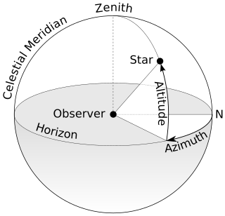
An azimuth is the angular measurement in a spherical coordinate system which represents the horizontal angle from a cardinal direction, most commonly north.

<span class="mw-page-title-main">Orbital inclination</span> Angle between a reference plane and the plane of an orbit

Orbital inclination measures the tilt of an object's orbit around a celestial body. It is expressed as the angle between a reference plane and the orbital plane or axis of direction of the orbiting object.

<span class="mw-page-title-main">Indirect fire</span> Weapons firing without line of sight on target

Indirect fire is aiming and firing a projectile without relying on a direct line of sight between the gun and its target, as in the case of direct fire. Aiming is performed by calculating azimuth and inclination, and may include correcting aim by observing the fall of shot and calculating new angles.

<span class="mw-page-title-main">Cylindrical coordinate system</span> 3-dimensional coordinate system

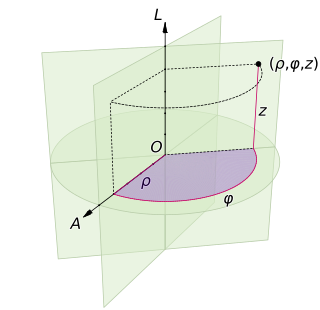
A cylindrical coordinate system is a three-dimensional coordinate system that specifies point positions by the distance from a chosen reference axis (axis L in the image opposite), the direction from the axis relative to a chosen reference direction (axis A), and the distance from a chosen reference plane perpendicular to the axis (plane containing the purple section). The latter distance is given as a positive or negative number depending on which side of the reference plane faces the point.

<span class="mw-page-title-main">Bearing (angle)</span> In navigation, horizontal angle between the direction of an object and another object

In navigation, bearing or azimuth is the horizontal angle between the direction of an object and north or another object. The angle value can be specified in various angular units, such as degrees, mils, or grad. More specifically:

<span class="mw-page-title-main">Theodolite</span> Optical surveying instrument

A theodolite is a precision optical instrument for measuring angles between designated visible points in the horizontal and vertical planes. The traditional use has been for land surveying, but it is also used extensively for building and infrastructure construction, and some specialized applications such as meteorology and rocket launching.

<span class="mw-page-title-main">Geologic map</span> Special-purpose map to show geological features

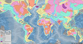
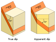
A geologic map or geological map is a special-purpose map made to show various geological features. Rock units or geologic strata are shown by color or symbols. Bedding planes and structural features such as faults, folds, are shown with strike and dip or trend and plunge symbols which give three-dimensional orientations features.

<span class="mw-page-title-main">Inclinometer</span> Instrument used to measure the inclination of a surface relative to local gravity

An inclinometer or clinometer is an instrument used for measuring angles of slope, elevation, or depression of an object with respect to gravity's direction. It is also known as a tilt indicator, tilt sensor, tilt meter, slope alert, slope gauge, gradient meter, gradiometer, level gauge, level meter, declinometer, and pitch & roll indicator. Clinometers measure both inclines and declines using three different units of measure: degrees, percentage points, and topos. The astrolabe is an example of an inclinometer that was used for celestial navigation and location of astronomical objects from ancient times to the Renaissance.

<span class="mw-page-title-main">Orientation (geometry)</span> Notion of pointing in a direction

In geometry, the orientation, attitude, bearing, direction, or angular position of an object – such as a line, plane or rigid body – is part of the description of how it is placed in the space it occupies. More specifically, it refers to the imaginary rotation that is needed to move the object from a reference placement to its current placement. A rotation may not be enough to reach the current placement, in which case it may be necessary to add an imaginary translation to change the object's position. The position and orientation together fully describe how the object is placed in space. The above-mentioned imaginary rotation and translation may be thought to occur in any order, as the orientation of an object does not change when it translates, and its position does not change when it rotates.

<span class="mw-page-title-main">Foliation (geology)</span>

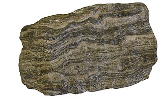
Foliation in geology refers to repetitive layering in metamorphic rocks. Each layer can be as thin as a sheet of paper, or over a meter in thickness. The word comes from the Latin folium, meaning "leaf", and refers to the sheet-like planar structure. It is caused by shearing forces, or differential pressure. The layers form parallel to the direction of the shear, or perpendicular to the direction of higher pressure. Nonfoliated metamorphic rocks are typically formed in the absence of significant differential pressure or shear. Foliation is common in rocks affected by the regional metamorphic compression typical of areas of mountain belt formation.

<span class="mw-page-title-main">Brunton compass</span> Precision compass made by Brunton, Inc. of Riverton, Wyoming

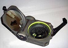
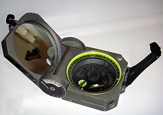
A Brunton compass, properly known as the Brunton Pocket Transit, is a precision compass made by Brunton, Inc. of Riverton, Wyoming. The instrument was patented in 1894 by Canadian-born geologist David W. Brunton. Unlike most modern compasses, the Brunton Pocket Transit utilizes magnetic induction damping rather than fluid to damp needle oscillation. Although Brunton, Inc. makes many other types of magnetic compasses, the Brunton Pocket Transit is a specialized instrument used widely by those needing to make accurate navigational and slope-angle measurements in the field. Users are primarily geologists, but archaeologists, environmental engineers, mining engineers and surveyors also make use of the Brunton's capabilities. The United States Army has adopted the Pocket Transit as the M2 Compass for use by crew-served artillery.

Lineations in structural geology are linear structural features within rocks. There are several types of lineations, intersection lineations, crenulation lineations, mineral lineations and stretching lineations being the most common. Lineation field measurements are recorded as map lines with a plunge angle and azimuth.

<span class="mw-page-title-main">Diver navigation</span> Underwater navigation by scuba divers

Diver navigation, termed "underwater navigation" by scuba divers, is a set of techniques—including observing natural features, the use of a compass, and surface observations—that divers use to navigate underwater. Free-divers do not spend enough time underwater for navigation to be important, and surface supplied divers are limited in the distance they can travel by the length of their umbilicals and are usually directed from the surface control point. On those occasions when they need to navigate they can use the same methods used by scuba divers.

<span class="mw-page-title-main">Cave survey</span>

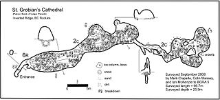
A cave survey is a map of all or part of a cave system, which may be produced to meet differing standards of accuracy depending on the cave conditions and equipment available underground. Cave surveying and cartography, i.e. the creation of an accurate, detailed map, is one of the most common technical activities undertaken within a cave and is a fundamental part of speleology. Surveys can be used to compare caves to each other by length, depth and volume, may reveal clues on speleogenesis, provide a spatial reference for other areas of scientific study and assist visitors with route-finding.

<span class="mw-page-title-main">Magnetic dip</span>

Magnetic dip, dip angle, or magnetic inclination is the angle made with the horizontal by the Earth's magnetic field lines. This angle varies at different points on the Earth's surface. Positive values of inclination indicate that the magnetic field of the Earth is pointing downward, into the Earth, at the point of measurement, and negative values indicate that it is pointing upward. The dip angle is in principle the angle made by the needle of a vertically held compass, though in practice ordinary compass needles may be weighted against dip or may be unable to move freely in the correct plane. The value can be measured more reliably with a special instrument typically known as a dip circle.

In structural geology, rake is formally defined as "the angle between a line [or a feature] and the strike line of the plane in which it is found", measured on the plane. The three-dimensional orientation of a line can be described with just a plunge and trend. The rake is a useful description of a line because often features (lines) follow along a planar surface. In these cases the rake can be used to describe the line's orientation in three dimensions relative to that planar surface. One might also expect to see this used when the particular line is hard to measure directly. The rake always sweeps down from the horizontal plane.

<span class="mw-page-title-main">Geological compass</span> Type of compass

There are a number of different specialized magnetic compasses used by geologists to measure orientation of geological structures, as they map in the field, to analyze and document the geometry of bedding planes, joints, and/or metamorphic foliations and lineations. In this aspect the most common device used to date is the analogue compass.

In forestry, a tree crown measurement is one of the tree measurements taken at the crown of a tree, which consists of the mass of foliage and branches growing outward from the trunk of the tree. The average crown spread is the average horizontal width of the crown, taken from dripline to dripline as one moves around the crown. The dripline is the outer boundary to the area located directly under the outer circumference of the tree branches. When the tree canopy gets wet, any excess water is shed to the ground along this dripline. Some listings will also list the maximum crown spread which represents the greatest width from dripline to dripline across the crown. Other crown measurements that are commonly taken include limb length, crown volume, and foliage density. Canopy mapping surveys the position and size of all of the limbs down to a certain size in the crown of the tree and is commonly used when measuring the overall wood volume of a tree.

References

  1. 1 2 3 4 5 6 7 8 "Measuring dip and strike". Geological Digressions. 2019-02-01. Archived from the original on 2021-12-29.
  2. 1 2 3 4 Panchuck, Karla (2018). "Measuring Geological Features". Physical Geology, First University of Saskatchewan Edition.
  3. 1 2 3 4 5 6 7 8 Waldron, John; Snyder, Morgan (2020). "Orientation of Structures". Geological Structures: A Practical Introduction. Open Education Alberta.
  4. Lahee, Federic H (1961). Field Geology (1 ed.). New York: McGraw-Hill. p. 6. ISBN   9780070358089.
  5. 1 2 Tarbuck, Edward J; Lutgens, Frederick K (2005). Earth: An Introduction to Physical Geology (8 ed.). Upper Saddle River, N.J.: Pearson / Prentice Hall. p. 308.
  6. PD-icon.svg "Dip". New International Encyclopedia . 1905.
  7. 1 2 3 Lisle, Richard J (2004). Geological Structures and Maps - A Practical Guide (3 ed.). pp. 2–6.
  8. "How to calculate an apparent dip from a real dip (and viceversa) using orthographic projection and trigonometry". Structural Geology. 2012-05-01. Archived from the original on 2021-06-11.
  9. "Digital Cartographic Standard for Geologic Map Symbolization". FGDC Geological Data Subcommittee. USGS. 2017-05-09.
  10. Clar, E (1954). "Ein zweikreisiger Geologen- und Bergmannskompaß zur Messung von Flächen und Linearen". Verhandlungen der Geologischen Bundesanstalt. 4.
  11. Weng Y.-H., Sun F.-S. & Grigsby J.D. (2012). "GeoTools: An android phone application in geology". Computers & Geosciences. 44: 24–30. Bibcode:2012CG.....44...24W. doi:10.1016/j.cageo.2012.02.027.
  12. "The Dipmeter Tool". KGS - Geological Log Analysis. Kansas State University. 2017-03-24. Archived from the original on 2021-04-25.

Further reading