Thin-film interference

Last updated
Thin-film interference caused by water-lipid boundary Lipid Islands on Soap Bubble (horizontal).jpg
Thin-film interference caused by water-lipid boundary

Thin-film interference is a natural phenomenon in which light waves reflected by the upper and lower boundaries of a thin film interfere with one another, increasing reflection at some wavelengths and decreasing it at others. When white light is incident on a thin film, this effect produces colorful reflections.

Contents

Thin-film interference explains the multiple colors seen in light reflected from soap bubbles and oil films on water. It is also the mechanism behind the action of antireflection coatings used on glasses and camera lenses. If the thickness of the film is much larger than the coherence length of the incident light, then the interference pattern will be washed out due to the linewidth of the light source.

The reflection from a thin film is typically not individual wavelengths as produced by a diffraction grating or prism, but rather are a mixture of various wavelengths. Therefore, the colors observed are rarely those of the rainbow, but rather browns, golds, turquoises, teals, bright blues, purples, and magentas. Studying the light reflected or transmitted by a thin film can reveal information about the thickness of the film or the effective refractive index of the film medium. Thin films have many commercial applications including anti-reflection coatings, mirrors, and optical filters.

Theory

Demonstration of the optical path length difference for light reflected from the upper and lower boundaries of a thin film. Thin film interference.svg
Demonstration of the optical path length difference for light reflected from the upper and lower boundaries of a thin film.
Thin-film interference caused by ITO defrosting coating on an Airbus cockpit window. LHcockpitWindow.jpg
Thin-film interference caused by ITO defrosting coating on an Airbus cockpit window.

In optics, a thin film is a layer of material with thickness in the sub-nanometer to micron range. As light strikes the surface of a film, it is either transmitted or reflected at the upper surface. Light that is transmitted reaches the bottom surface and may once again be transmitted or reflected. The Fresnel equations provide a quantitative description of how much of the light will be transmitted or reflected at an interface. The light reflected from the upper and lower surfaces will interfere. The degree of constructive or destructive interference between the two light waves depends on the difference in their phase. This difference in turn depends on the thickness of the film layer, the refractive index of the film, and the angle of incidence of the original wave on the film. Additionally, a phase shift of 180° or radians may be introduced upon reflection at a boundary depending on the refractive indices of the materials on either side of the boundary. This phase shift occurs if the refractive index of the medium the light is travelling through is less than the refractive index of the material it is striking. In other words, if and the light is travelling from material 1 to material 2, then a phase shift occurs upon reflection. The pattern of light that results from this interference can appear either as light and dark bands or as colorful bands depending upon the source of the incident light.

Consider light incident on a thin film and reflected by both the upper and lower boundaries. The optical path difference (OPD) of the reflected light must be calculated in order to determine the condition for interference. Referring to the ray diagram above, the OPD between the two waves is the following:

Where,

Using Snell's law,

Interference will be constructive if the optical path difference is equal to an integer multiple of the wavelength of light, .

This condition may change after considering possible phase shifts that occur upon reflection.

Monochromatic source

Gasoline on water shows a pattern of bright and dark fringes when illuminated with 589nm laser light. Thin film interference gasoline on water @ 589nm.jpg
Gasoline on water shows a pattern of bright and dark fringes when illuminated with 589nm laser light.

Where incident light is monochromatic in nature, interference patterns appear as light and dark bands. Light bands correspond to regions at which constructive interference is occurring between the reflected waves and dark bands correspond to destructive interference regions. As the thickness of the film varies from one location to another, the interference may change from constructive to destructive. A good example of this phenomenon, termed "Newton's rings", demonstrates the interference pattern that results when light is reflected from a spherical surface adjacent to a flat surface. Concentric rings are observed when the surface is illuminated with monochromatic light. This phenomenon is used with optical flats to measure the shape and flatness of surfaces.

Broadband source

If the incident light is broadband, or white, such as light from the sun, interference patterns appear as colorful bands. Different wavelengths of light create constructive interference for different film thicknesses. Different regions of the film appear in different colors depending on the local film thickness.

Phase interaction

Constructive phase interaction Thin film interference phase 1.svg
Constructive phase interaction
Destructive phase interaction Thin film interference phase 2.svg
Destructive phase interaction

The figures show two incident light beams (A and B). Each beam produces a reflected beam (dashed). The reflections of interest are beam A’s reflection off of the lower surface and beam B’s reflection off of the upper surface. These reflected beams combine to produce a resultant beam (C). If the reflected beams are in phase (as in the first figure) the resultant beam is relatively strong. If, on the other hand, the reflected beams have opposite phase, the resulting beam is attenuated (as in the second figure).

The phase relationship of the two reflected beams depends on the relationship between the wavelength of beam A in the film, and the film's thickness. If the total distance beam A travels in the film is an integer multiple of the wavelength of the beam in the film, then the two reflected beams are in phase and constructively interfere (as depicted in the first figure). If the distance traveled by beam A is an odd integer multiple of the half wavelength of light in the film, the beams destructively interfere (as in the second figure). Thus, the film shown in these figures reflects more strongly at the wavelength of the light beam in the first figure, and less strongly at that of the beam in the second figure.

Examples

The type of interference that occurs when light is reflected from a thin film is dependent upon the wavelength and angle of the incident light, the thickness of the film, the refractive indices of the material on either side of the film, and the index of the film medium. Various possible film configurations and the related equations are explained in more detail in the examples below.

Soap bubble

Light incident on a soap film in air Thin film interference - soap bubble.gif
Light incident on a soap film in air

In the case of a soap bubble, light travels through air and strikes a soap film. The air has a refractive index of 1 () and the film has an index that is larger than 1 (). The reflection that occurs at the upper boundary of the film (the air-film boundary) will introduce a 180° phase shift in the reflected wave because the refractive index of the air is less than the index of the film (). Light that is transmitted at the upper air-film interface will continue to the lower film-air interface where it can be reflected or transmitted. The reflection that occurs at this boundary will not change the phase of the reflected wave because . The condition for interference for a soap bubble is the following:

  for constructive interference of reflected light
  for destructive interference of reflected light

Where is the film thickness, is the refractive index of the film, is the angle of incidence of the wave on the lower boundary, is an integer, and is the wavelength of light.

Oil film

Light incident on an oil film on water Thin film interference - oil film.gif
Light incident on an oil film on water

In the case of a thin oil film, a layer of oil sits on top of a layer of water. The oil may have an index of refraction near 1.5 and the water has an index of 1.33. As in the case of the soap bubble, the materials on either side of the oil film (air and water) both have refractive indices that are less than the index of the film. . There will be a phase shift upon reflection from the upper boundary because but no shift upon reflection from the lower boundary because . The equations for interference will be the same.

  for constructive interference of reflected light
  for destructive interference of reflected light

Anti-reflection coatings

Light incident on an anti-reflection coating on glass Thin film interference - anti-reflection coating.gif
Light incident on an anti-reflection coating on glass

An anti-reflection coating eliminates reflected light and maximizes transmitted light in an optical system. A film is designed such that reflected light produces destructive interference and transmitted light produces constructive interference for a given wavelength of light. In the simplest implementation of such a coating, the film is created so that its optical thickness is a quarter-wavelength of the incident light and its refractive index is greater than the index of air and less than the index of glass.

A 180° phase shift will be induced upon reflection at both the top and bottom interfaces of the film because and . The equations for interference of the reflected light are:

  for constructive interference
  for destructive interference

If the optical thickness is equal to a quarter-wavelength of the incident light and if the light strikes the film at normal incidence , the reflected waves will be completely out of phase and will destructively interfere. Further reduction in reflection is possible by adding more layers, each designed to match a specific wavelength of light.

Interference of transmitted light is completely constructive for these films.

In nature

Structural coloration due to thin-film layers is common in the natural world. The wings of many insects act as thin films because of their minimal thickness. This is clearly visible in the wings of many flies and wasps. In butterflies, the thin-film optics are visible when the wing itself is not covered by pigmented wing scales, which is the case in the blue wing spots of the Aglais io butterfly. [1] The glossy appearance of buttercup flowers is also due to a thin film [2] [3] as well as the shiny breast feathers of the bird of paradise. [4]

Applications

An antireflection-coated optical window. At a 45deg angle the coating is slightly thicker to the incident light, causing the center wavelength to shift toward the red and reflections appear at the violet end of the spectrum. At 0deg, for which this coating was designed, almost no reflection is observed. Antireflection coating split pic.jpg
An antireflection-coated optical window. At a 45° angle the coating is slightly thicker to the incident light, causing the center wavelength to shift toward the red and reflections appear at the violet end of the spectrum. At 0°, for which this coating was designed, almost no reflection is observed.

Thin films are used commercially in anti-reflection coatings, mirrors, and optical filters. They can be engineered to control the amount of light reflected or transmitted at a surface for a given wavelength. A Fabry–Pérot etalon takes advantage of thin film interference to selectively choose which wavelengths of light are allowed to transmit through the device. These films are created through deposition processes in which material is added to a substrate in a controlled manner. Methods include chemical vapor deposition and various physical vapor deposition techniques.

Thin films are also found in nature. Many animals have a layer of tissue behind the retina, the Tapetum lucidum, that aids in light collecting. The effects of thin-film interference can also be seen in oil slicks and soap bubbles. The reflectance spectrum of a thin-film features distinct oscillations and the extrema of the spectrum can be used to calculate the thickness of the thin-film. [1]

Ellipsometry is a technique that is often used to measure properties of thin films. In a typical ellipsometry experiment polarized light is reflected off a film surface and is measured by a detector. The complex reflectance ratio, , of the system is measured. A model analysis in then conducted in which this information is used to determine film layer thicknesses and refractive indices.

Dual polarisation interferometry is an emerging technique for measuring refractive index and thickness of molecular scale thin films and how these change when stimulated.

History

Tempering colors are produced when steel is heated and a thin film of iron oxide forms on the surface. The color indicates the temperature the steel reached, which made this one of the earliest practical uses of thin-film interference. Tempering standards used in blacksmithing.JPG
Tempering colors are produced when steel is heated and a thin film of iron oxide forms on the surface. The color indicates the temperature the steel reached, which made this one of the earliest practical uses of thin-film interference.
Iridescent interference colors in an oil film Newton Mess Iridescence.jpg
Iridescent interference colors in an oil film

Iridescence caused by thin-film interference is a commonly observed phenomenon in nature, being found in a variety of plants and animals. One of the first known studies of this phenomenon was conducted by Robert Hooke in 1665. In Micrographia , Hooke postulated that the iridescence in peacock feathers was caused by thin, alternating layers of plate and air. In 1704, Isaac Newton stated in his book, Opticks , that the iridescence in a peacock feather was due to the fact that the transparent layers in the feather were so thin. [5] In 1801, Thomas Young provided the first explanation of constructive and destructive interference. Young's contribution went largely unnoticed until the work of Augustin Fresnel, who helped to establish the wave theory of light in 1816. [6] However, very little explanation could be made of the iridescence until the 1870s, when James Maxwell and Heinrich Hertz helped to explain the electromagnetic nature of light. [5] After the invention of the Fabry–Perot interferometer, in 1899, the mechanisms of thin-film interference could be demonstrated on a larger scale. [6]

In much of the early work, scientists tried to explain iridescence, in animals like peacocks and scarab beetles, as some form of surface color, such as a dye or pigment that might alter the light when reflected from different angles. In 1919, Lord Rayleigh proposed that the bright, changing colors were not caused by dyes or pigments, but by microscopic structures, which he termed "structural colors." [5] In 1923, C. W. Mason noted that the barbules in the peacock feather were made from very thin layers. Some of these layers were colored while others were transparent. He noticed that pressing the barbule would shift the color toward the blue, while swelling it with a chemical would shift it toward the red. He also found that bleaching the pigments from the feathers did not remove the iridescence. This helped to dispel the surface color theory and reinforce the structural color theory. [7]

In 1925, Ernest Merritt, in his paper A Spectrophotometric Study of Certain Cases of Structural Color, first described the process of thin-film interference as an explanation for the iridescence. The first examination of iridescent feathers by an electron microscope occurred in 1939, revealing complex thin-film structures, while an examination of the morpho butterfly, in 1942, revealed an extremely tiny array of thin-film structures on the nanometer scale. [5]

The first production of thin-film coatings occurred quite by accident. In 1817, Joseph Fraunhofer discovered that, by tarnishing glass with nitric acid, he could reduce the reflections on the surface. In 1819, after watching a layer of alcohol evaporate from a sheet of glass, Fraunhofer noted that colors appeared just before the liquid evaporated completely, deducing that any thin film of transparent material will produce colors. [6]

Little advancement was made in thin-film coating technology until 1936, when John Strong began evaporating fluorite in order to make anti-reflection coatings on glass. During the 1930s, improvements in vacuum pumps made vacuum deposition methods, like sputtering, possible. In 1939, Walter H. Geffcken created the first interference filters using dielectric coatings. [6]

See also

Related Research Articles

<span class="mw-page-title-main">Diffraction</span> Phenomenon of the motion of waves

Diffraction is the interference or bending of waves around the corners of an obstacle or through an aperture into the region of geometrical shadow of the obstacle/aperture. The diffracting object or aperture effectively becomes a secondary source of the propagating wave. Italian scientist Francesco Maria Grimaldi coined the word diffraction and was the first to record accurate observations of the phenomenon in 1660.

<span class="mw-page-title-main">Wave interference</span> Phenomenon resulting from the superposition of two waves

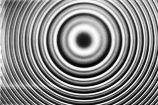
In physics, interference is a phenomenon in which two coherent waves are combined by adding their intensities or displacements with due consideration for their phase difference. The resultant wave may have greater intensity or lower amplitude if the two waves are in phase or out of phase, respectively. Interference effects can be observed with all types of waves, for example, light, radio, acoustic, surface water waves, gravity waves, or matter waves as well as in loudspeakers as electrical waves.

<span class="mw-page-title-main">Refractive index</span> Ratio of the speed of light in vacuum to that in the medium

In optics, the refractive index of an optical medium is a dimensionless number that gives the indication of the light bending ability of that medium.

<span class="mw-page-title-main">Wavelength</span> Distance over which a waves shape repeats

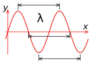
In physics and mathematics, wavelength or spatial period of a wave or periodic function is the distance over which the wave's shape repeats. In other words, it is the distance between consecutive corresponding points of the same phase on the wave, such as two adjacent crests, troughs, or zero crossings. Wavelength is a characteristic of both traveling waves and standing waves, as well as other spatial wave patterns. The inverse of the wavelength is called the spatial frequency. Wavelength is commonly designated by the Greek letter lambda (λ). The term "wavelength" is also sometimes applied to modulated waves, and to the sinusoidal envelopes of modulated waves or waves formed by interference of several sinusoids.

<span class="mw-page-title-main">Numerical aperture</span> Characteristic of an optical system

In optics, the numerical aperture (NA) of an optical system is a dimensionless number that characterizes the range of angles over which the system can accept or emit light. By incorporating index of refraction in its definition, NA has the property that it is constant for a beam as it goes from one material to another, provided there is no refractive power at the interface. The exact definition of the term varies slightly between different areas of optics. Numerical aperture is commonly used in microscopy to describe the acceptance cone of an objective, and in fiber optics, in which it describes the range of angles within which light that is incident on the fiber will be transmitted along it.

<span class="mw-page-title-main">Snell's law</span> Formula for refraction angles

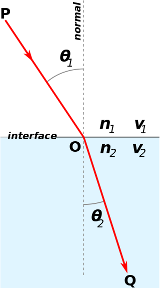
Snell's law is a formula used to describe the relationship between the angles of incidence and refraction, when referring to light or other waves passing through a boundary between two different isotropic media, such as water, glass, or air. In optics, the law is used in ray tracing to compute the angles of incidence or refraction, and in experimental optics to find the refractive index of a material. The law is also satisfied in meta-materials, which allow light to be bent "backward" at a negative angle of refraction with a negative refractive index.

<span class="mw-page-title-main">Fabry–Pérot interferometer</span> Optical device with parallel mirrors

In optics, a Fabry–Pérot interferometer (FPI) or etalon is an optical cavity made from two parallel reflecting surfaces. Optical waves can pass through the optical cavity only when they are in resonance with it. It is named after Charles Fabry and Alfred Perot, who developed the instrument in 1899. Etalon is from the French étalon, meaning "measuring gauge" or "standard".

In many areas of science, Bragg's law, Wulff–Bragg's condition, or Laue–Bragg interference are a special case of Laue diffraction, giving the angles for coherent scattering of waves from a large crystal lattice. It describes how the superposition of wave fronts scattered by lattice planes leads to a strict relation between the wavelength and scattering angle. This law was initially formulated for X-rays, but it also applies to all types of matter waves including neutron and electron waves if there are a large number of atoms, as well as visible light with artificial periodic microscale lattices.

<span class="mw-page-title-main">Optical coating</span> Material which alters light reflection or transmission on optics

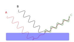
An optical coating is one or more thin layers of material deposited on an optical component such as a lens, prism or mirror, which alters the way in which the optic reflects and transmits light. These coatings have become a key technology in the field of optics. One type of optical coating is an anti-reflective coating, which reduces unwanted reflections from surfaces, and is commonly used on spectacle and camera lenses. Another type is the high-reflector coating, which can be used to produce mirrors that reflect greater than 99.99% of the light that falls on them. More complex optical coatings exhibit high reflection over some range of wavelengths, and anti-reflection over another range, allowing the production of dichroic thin-film filters.

In optics, the Fraunhofer diffraction equation is used to model the diffraction of waves when plane waves are incident on a diffracting object, and the diffraction pattern is viewed at a sufficiently long distance from the object, and also when it is viewed at the focal plane of an imaging lens. In contrast, the diffraction pattern created near the diffracting object and is given by the Fresnel diffraction equation.

In optics, an ARROW is a type of waveguide that uses the principle of thin-film interference to guide light with low loss. It is formed from an anti-resonant Fabry–Pérot reflector. The optical mode is leaky, but relatively low-loss propagation can be achieved by making the Fabry–Pérot reflector of sufficiently high quality or small size.

<span class="mw-page-title-main">Anti-reflective coating</span> Optical coating that reduces reflection

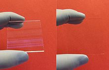
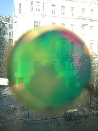
An antireflective, antiglare or anti-reflection (AR) coating is a type of optical coating applied to the surface of lenses, other optical elements, and photovoltaic cells to reduce reflection. In typical imaging systems, this improves the efficiency since less light is lost due to reflection. In complex systems such as cameras, binoculars, telescopes, and microscopes the reduction in reflections also improves the contrast of the image by elimination of stray light. This is especially important in planetary astronomy. In other applications, the primary benefit is the elimination of the reflection itself, such as a coating on eyeglass lenses that makes the eyes of the wearer more visible to others, or a coating to reduce the glint from a covert viewer's binoculars or telescopic sight.

<span class="mw-page-title-main">Gires–Tournois etalon</span>

In optics, a Gires–Tournois etalon is a transparent plate with two reflecting surfaces, one of which has very high reflectivity, ideally unity. Due to multiple-beam interference, light incident on a Gires–Tournois etalon is (almost) completely reflected, but has an effective phase shift that depends strongly on the wavelength of the light.

<span class="mw-page-title-main">Shearing interferometer</span>

The shearing interferometer is an extremely simple means to observe interference and to use this phenomenon to test the collimation of light beams, especially from laser sources which have a coherence length which is usually significantly longer than the thickness of the shear plate so that the basic condition for interference is fulfilled.

A prism coupler is a prism designed to couple a substantial fraction of the power contained in a beam of light into a thin film to be used as a waveguide without the need for precision polishing of the edge of the film, without the need for sub-micrometer alignment precision of the beam and the edge of the film, and without the need for matching the numerical aperture of the beam to the film. Using a prism coupler, a beam coupled into a thin film can have a diameter hundreds of times the thickness of the film. Invention of the coupler contributed to the initiation of a field of study known as integrated optics.

Fluorescence interference contrast (FLIC) microscopy is a microscopic technique developed to achieve z-resolution on the nanometer scale.

<span class="mw-page-title-main">Acousto-optics</span> The study of sound and light interaction

Acousto-optics is a branch of physics that studies the interactions between sound waves and light waves, especially the diffraction of laser light by ultrasound through an ultrasonic grating.

Volume holograms are holograms where the thickness of the recording material is much larger than the light wavelength used for recording. In this case diffraction of light from the hologram is possible only as Bragg diffraction, i.e., the light has to have the right wavelength (color) and the wave must have the right shape. Volume holograms are also called thick holograms or Bragg holograms.

Free spectral range (FSR) is the spacing in optical frequency or wavelength between two successive reflected or transmitted optical intensity maxima or minima of an interferometer or diffractive optical element.

<span class="mw-page-title-main">Rugate filter</span> Dielectric mirror that selectively reflects a particular wavelength range of light

A rugate filter, also known as a gradient-index filter, is an optical filter based on a dielectric mirror that selectively reflects specific wavelength ranges of light. This effect is achieved by a periodic, continuous change of the refractive index of the dielectric coating. The word "rugate" is derived from corrugated structures found in nature, which also selectively reflect certain wavelength ranges of light, for example the wings of the Morpho butterfly.

References

  1. 1 2 3 Stavenga, D. G. (2014). "Thin Film and Multilayer Optics Cause Structural Colors of Many Insects and Birds". Materials Today: Proceedings. 1: 109–121. doi:10.1016/j.matpr.2014.09.007.
  2. 1 2 Van Der Kooi, C. J.; Elzenga, J.T.M.; Dijksterhuis, J.; Stavenga, D.G. (2017). "Functional optics of glossy buttercup flowers". Journal of the Royal Society Interface. 14 (127): 20160933. doi:10.1098/rsif.2016.0933. PMC   5332578 . PMID   28228540.
  3. Van Der Kooi, C. J.; Wilts, B. D.; Leertouwer, H. L.; Staal, M.; Elzenga, J. T. M.; Stavenga, D. G. (2014). "Iridescent flowers? Contribution of surface structures to optical signaling" (PDF). New Phytologist. 203 (2): 667–73. doi: 10.1111/nph.12808 . PMID   24713039.
  4. Stavenga, D. G.; Leertouwer, H. L.; Marshall, N. J.; Osorio, D. (2010). "Dramatic colour changes in a bird of paradise caused by uniquely structured breast feather barbules". Proceedings of the Royal Society B: Biological Sciences. 278 (1715): 2098–104. doi:10.1098/rspb.2010.2293. PMC   3107630 . PMID   21159676.
  5. 1 2 3 4 Structural colors in the realm of nature By Shūichi Kinoshita – World Scientific Publishing 2008 pages 3–6
  6. 1 2 3 4 Thin-film optical filters By Hugh Angus Macleod – Institute of Physics Publishing 2001 Pages 1–4
  7. Structural colors in the realm of nature By Shūichi Kinoshita - World Scientific Publishing 2008 Page 165-167

Further reading