Triangle strip

Last updated

In computer graphics, a triangle strip is a subset of triangles in a triangle mesh with shared vertices, and is a more memory-efficient method of storing information about the mesh. They are more efficient than un-indexed lists of triangles, but usually equally fast or slower than indexed triangle lists. [1] [2] The primary reason to use triangle strips is to reduce the amount of data needed to create a series of triangles. The number of vertices stored in memory is reduced from 3N to N + 2, where N is the number of triangles to be drawn. This allows for less use of disk space, as well as making them faster to load into RAM.

Contents

Diagram of four triangles, 1, 2, 3, and 4, with vertices A, B, C, D, E, and F. Triangle Strip.svg
Diagram of four triangles, 1, 2, 3, and 4, with vertices A, B, C, D, E, and F.

For example, the four triangles in the diagram, without using triangle strips, would have to be stored and interpreted as four separate triangles: ABC, CBD, CDE, and EDF. However, using a triangle strip, they can be stored simply as a sequence of vertices ABCDEF. This sequence would be decoded as a set of triangles with vertices at ABC, BCD, CDE and DEF - although the exact order that the vertices are read will not be in left-to-right order as this would result in adjacent triangles facing alternating directions.

OpenGL implementation

Model of two triangles drawn in OpenGL using triangle strips. Triangle Strip In OpenGL.svg
Model of two triangles drawn in OpenGL using triangle strips.

OpenGL has built-in support for triangle strips. Fixed function OpenGL (deprecated in OpenGL 3.0) has support for triangle strips using immediate mode and the glBegin(), glVertex*(), and glEnd() functions. Newer versions support triangle strips using glDrawElements and glDrawArrays.

To draw a triangle strip using immediate mode OpenGL, glBegin() must be passed the argument GL_TRIANGLE_STRIP, which notifies OpenGL a triangle strip is about to be drawn. The glVertex*() family of functions specify the coordinates for each vertex in the triangle strip. For more information, consult The OpenGL Redbook. [3]

To draw the triangle strip in the diagram using immediate mode OpenGL, the code is as follows:

//Vertices below are in Clockwise orientation//Default setting for glFrontFace is Counter-clockwiseglFrontFace(GL_CW);glBegin(GL_TRIANGLE_STRIP);glVertex3f(0.0f,0.0f,0.0f);//vertex 1glVertex3f(0.0f,0.5f,0.0f);//vertex 2glVertex3f(0.5f,0.0f,0.0f);//vertex 3glVertex3f(1.0f,0.5f,0.0f);//vertex 4glEnd();

Note that only one additional vertex is needed to draw the second triangle. In OpenGL, the order in which the vertices are specified is important so that surface normals are consistent.

Quoting directly from the OpenGL Programming Guide:

GL_TRIANGLE_STRIP

Triangles Strip In OpenGL.svg

Draws a series of triangles (three-sided polygons) using vertices v0, v1, v2, then v2, v1, v3 (note the order), then v2, v3, v4, and so on. The ordering is to ensure that the triangles are all drawn with the same orientation so that the strip can correctly form part of a surface.

It's even clearer within the manual pages: [4]

Draws a connected group of triangles. One triangle is defined for each vertex presented after the first two vertices. For odd n, vertices n, n + 1, and n + 2 define triangle n. For even n, vertices n + 1, n, and n + 2 define triangle n. n – 2 triangles are drawn.

Note that n starts at 1. The above code sample and diagram demonstrate triangles drawn in a clockwise orientation. For those to be considered front-facing, a preceding call to glFrontFace(GL_CW) is necessary, which otherwise has an initial value of GL_CCW (meaning that triangles drawn counter-clockwise are front-facing by default). [5] This is significant if glEnable(GL_CULL_FACE) and glCullFace(GL_BACK) are already active (GL_BACK by default [6] ), because back-facing triangles will be culled, so will not be drawn and will not appear on-screen at all. [7]

Properties and construction

It follows from definition that a subsequence of vertices of a triangle strip also represents a triangle strip. However, if this substrip starts at an even (with 1-based counting) vertex, then the resulting triangles will change their orientation. For example a substrip BCDEF would represent triangles: BCD,CED,DEF.

Similarly, reversal of strips’ vertices will result in the same set of triangles if the strip has an even number of vertices. (e.g. strip FEDCBA will represent the same triangles FED,ECD,DCB,CAB as the original strip). However, if a strip has an odd number of vertices then the reversed strip will represent triangles with opposite orientation. For example, reversal of a strip ABCDE will result in strip EDCBA which represents triangles EDC, DBC, CBA).

Converting a general polygon mesh to a single long strip was until recently generally not possible. Usually the triangle strips are analogous to a set of edge loops, and poles on the model are represented by triangle fans. Tools such as Stripe [8] or FTSG [9] represent the model as several strips. Optimally grouping a set of triangles into sequential strips has been proven NP-complete. [10]

Alternatively, a complete object can be described as a degenerate strip, which contains zero-area triangles that the processing software or hardware will discard. The degenerate triangles effectively introduce discontinuities or "jumps" to the strip. For example, the mesh in the diagram could also be represented as ABCDDFFEDC, which would be interpreted as triangles ABC CBD CDD DDF DFF FFE FED DEC (degenerate triangles marked with italics). Notice how this strip first builds two triangles from the left, then restarts and builds the remaining two from the right.

While discontinuities in triangle strips can always be implemented by resending vertices, APIs sometimes explicitly support this feature. IRIS GL supported Swaps (flipping two subsequent vertices in a strip), a feature relied on by early algorithms such as the SGI algorithm. Recently OpenGL/DirectX can render multiple triangle strips without degenerated triangles using Primitive Restart feature.

Curve tracing using triangle strip Simplicial.gif
Curve tracing using triangle strip

Related Research Articles

<span class="mw-page-title-main">Shading</span> Depicting depth through varying levels of darkness

Shading refers to the depiction of depth perception in 3D models or illustrations by varying the level of darkness. Shading tries to approximate local behavior of light on the object's surface and is not to be confused with techniques of adding shadows, such as shadow mapping or shadow volumes, which fall under global behavior of light.

<span class="mw-page-title-main">Hidden-surface determination</span> Visibility in 3D computer graphics

In 3D computer graphics, hidden-surface determination is the process of identifying what surfaces and parts of surfaces can be seen from a particular viewing angle. A hidden-surface determination algorithm is a solution to the visibility problem, which was one of the first major problems in the field of 3D computer graphics. The process of hidden-surface determination is sometimes called hiding, and such an algorithm is sometimes called a hider. When referring to line rendering it is known as hidden-line removal. Hidden-surface determination is necessary to render a scene correctly, so that one may not view features hidden behind the model itself, allowing only the naturally viewable portion of the graphic to be visible.

<span class="mw-page-title-main">Polygon mesh</span> Set of polygons to define a 3D model

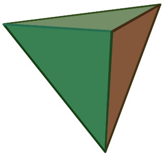
In 3D computer graphics and solid modeling, a polygon mesh is a collection of vertices, edges and faces that defines the shape of a polyhedral object. The faces usually consist of triangles, quadrilaterals (quads), or other simple convex polygons (n-gons), since this simplifies rendering, but may also be more generally composed of concave polygons, or even polygons with holes.

<span class="mw-page-title-main">Shader</span> Type of program in a graphical processing unit (GPU)

In computer graphics, a shader is a computer program that calculates the appropriate levels of light, darkness, and color during the rendering of a 3D scene—a process known as shading. Shaders have evolved to perform a variety of specialized functions in computer graphics special effects and video post-processing, as well as general-purpose computing on graphics processing units.

OBJ is a geometry definition file format first developed by Wavefront Technologies for its Advanced Visualizer animation package. The file format is open and has been adopted by other 3D graphics application vendors.

<span class="mw-page-title-main">Back-face culling</span> Only rendering polygons facing towards the camera

In computer graphics, back-face culling determines whether a polygon of a graphical object is drawn. It is a step in the graphical pipeline that tests whether the points in the polygon appear in clockwise or counter-clockwise order when projected onto the screen. If the user has specified that front-facing polygons have a clockwise winding, but the polygon projected on the screen has a counter-clockwise winding then it has been rotated to face away from the camera and will not be drawn.

<span class="mw-page-title-main">Polygonal modeling</span> Object modeling method

In 3D computer graphics, polygonal modeling is an approach for modeling objects by representing or approximating their surfaces using polygon meshes. Polygonal modeling is well suited to scanline rendering and is therefore the method of choice for real-time computer graphics. Alternate methods of representing 3D objects include NURBS surfaces, subdivision surfaces, and equation-based representations used in ray tracers.

<span class="mw-page-title-main">Uniform polyhedron</span> Isogonal polyhedron with regular faces

In geometry, a uniform polyhedron has regular polygons as faces and is vertex-transitive. It follows that all vertices are congruent.

A quad-edge data structure is a computer representation of the topology of a two-dimensional or three-dimensional map, that is, a graph drawn on a (closed) surface. It was first described by Jorge Stolfi and Leonidas J. Guibas. It is a variant of the earlier winged edge data structure.

<span class="mw-page-title-main">Triangle mesh</span> Polygon mesh composed of triangles

In computer graphics, a triangle mesh is a type of polygon mesh. It comprises a set of triangles that are connected by their common edges or vertices.

PLY is a computer file format known as the Polygon File Format or the Stanford Triangle Format. It was principally designed to store three-dimensional data from 3D scanners. The data storage format supports a relatively simple description of a single object as a list of nominally flat polygons. A variety of properties can be stored, including color and transparency, surface normals, texture coordinates and data confidence values. The format permits one to have different properties for the front and back of a polygon.

Java Binding for the OpenGL API is a JSR API specification for the Java Platform, Standard Edition which allows to use OpenGL on the Java. There is also Java Binding for the OpenGL ES API for the Java Platform, Micro Edition.

In geometry, a uniform tiling is a tessellation of the plane by regular polygon faces with the restriction of being vertex-transitive.

A vertex buffer object (VBO) is an OpenGL feature that provides methods for uploading vertex data to the video device for non-immediate-mode rendering. VBOs offer substantial performance gains over immediate mode rendering primarily because the data reside in video device memory rather than system memory and so it can be rendered directly by the video device. These are equivalent to vertex buffers in Direct3D.

Additive manufacturing file format (AMF) is an open standard for describing objects for additive manufacturing processes such as 3D printing. The official ISO/ASTM 52915:2016 standard is an XML-based format designed to allow any computer-aided design software to describe the shape and composition of any 3D object to be fabricated on any 3D printer via a computer-aided manufacturing software. Unlike its predecessor STL format, AMF has native support for color, materials, lattices, and constellations.

In geometry of 4 dimensions or higher, a double pyramid, duopyramid, or fusil is a polytope constructed by 2 orthogonal polytopes with edges connecting all pairs of vertices between the two. The term fusil is used by Norman Johnson as a rhombic-shape. The term duopyramid was used by George Olshevsky, as the dual of a duoprism.

In graph drawing and geometric graph theory, a Tutte embedding or barycentric embedding of a simple, 3-vertex-connected, planar graph is a crossing-free straight-line embedding with the properties that the outer face is a convex polygon and that each interior vertex is at the average of its neighbors' positions. If the outer polygon is fixed, this condition on the interior vertices determines their position uniquely as the solution to a system of linear equations. Solving the equations geometrically produces a planar embedding. Tutte's spring theorem, proven by W. T. Tutte (1963), states that this unique solution is always crossing-free, and more strongly that every face of the resulting planar embedding is convex. It is called the spring theorem because such an embedding can be found as the equilibrium position for a system of springs representing the edges of the graph.

3D Manufacturing Format or 3MF is an open source file format standard developed and published by the 3MF Consortium.

This is a glossary of terms relating to computer graphics.

<span class="mw-page-title-main">Fan triangulation</span> Method of triangulating complex polygons

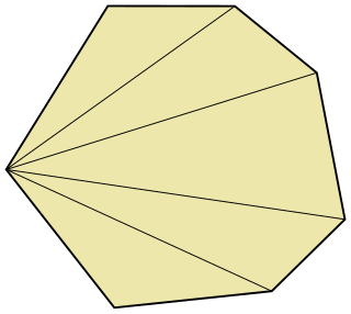
In computational geometry, a fan triangulation is a simple way to triangulate a polygon by choosing a vertex and drawing edges to all of the other vertices of the polygon. Not every polygon can be triangulated this way, so this method is usually only used for convex polygons.

References

  1. "Documentation Archive".
  2. "The Hacks of Life: To Strip or Not to Strip". 31 January 2010.
  3. The OpenGL Redbook
  4. "GlBegin".
  5. glFrontFace
  6. glCullFace
  7. OpenGL FAQ / 10 Clipping, Culling, and Visibility Testing
  8. Azanli, Elvir. Stripe, retrieved on March 28, 2007.
  9. Xiang, Xinyu. FTSG, retrieved on January 21, 2011. (link is no longer valid)
  10. Regina Estkowski, Joseph S. B. Mitchell, Xinyu Xiang. Optimal decomposition of polygonal models into triangle strips. In Proceedings of Symposium on Computational Geometry'2002. pp.254~263 url=http://www.ams.sunysb.edu/~jsbm/papers/p151-mitchell.pdf url=http://portal.acm.org/citation.cfm?id=513431

See also