Unbalanced line

Last updated

A multicore cable able to support 25 unbalanced transmission lines Cable-multicore-25x014mm-0a.jpg
A multicore cable able to support 25 unbalanced transmission lines

In telecommunications and electrical engineering in general, an unbalanced line is a pair of conductors intended to carry electrical signals, which have unequal impedances along their lengths and to ground and other circuits. Examples of unbalanced lines are coaxial cable or the historic earth return system invented for the telegraph, but rarely used today. Unbalanced lines are to be contrasted with balanced lines, such as twin-lead or twisted pair which use two identical conductors to maintain impedance balance throughout the line. Balanced and unbalanced lines can be interfaced using a device called a balun.

Contents

The chief advantage of the unbalanced line format is cost efficiency. Multiple unbalanced lines can be provided in the same cable with one conductor per line plus a single common return conductor, typically the cable shielding. Likewise, multiple microstrip circuits can all use the same ground plane for the return path. This compares well with balanced cabling which requires two conductors for each line, nearly twice as many. Another benefit of unbalanced lines is that they do not require more expensive, balanced driver and receiver circuits to operate correctly.

Unbalanced lines are sometimes confused with single-ended signalling, but these are entirely separate concepts. The former is a cabling scheme while the latter is a signalling scheme. However, single-ended signalling is commonly sent over unbalanced lines. Unbalanced lines are not to be confused with single-wire transmission lines which do not use a return path at all.

General description

Any line that has a different impedance of the return path may be considered an unbalanced line. However, unbalanced lines usually consist of a conductor that is considered the signal line and another conductor that is grounded, or is ground itself. The ground conductor often takes the form of a ground plane or the screen of a cable. The ground conductor may be, and often is, common to multiple independent circuits. For this reason the ground conductor may be referred to as common.

Telegraph lines

Telegraph lines on an Oppenheimer pole outside the historic Alice Springs telegraph station on the now disused Australian Overland Telegraph Line Alice Springs Telegraph Station 4.jpg
Telegraph lines on an Oppenheimer pole outside the historic Alice Springs telegraph station on the now disused Australian Overland Telegraph Line

The earliest use of unbalanced transmission lines was for electric telegraph communications. These consisted of single wires strung between poles. The return path for the current was originally provided by a separate conductor. Some early telegraph systems, such as Schilling's 1832 experimental needle telegraph and the 1837 Cooke & Wheatstone five-needle telegraph used by British railways required multiple code wires. Essentially, they were parallel bus coding. In these systems the cost of the return conductor was not so significant (one conductor in seven for Schilling's earliest needle telegraph [1] and one conductor in six for the Cooke and Wheatstone telegraph [2] ) but the number of coding conductors was progressively reduced with improved systems. Soon only one coding wire was required with the data being transmitted serially. Important examples of these single-wire systems were the Morse telegraph (1837) and the Cooke & Wheatstone single-needle telegraph (1843). In such systems the cost of a return conductor was fully 50 percent of the cable costs. It was discovered that a return conductor could be replaced with a return path through the Earth using grounding spikes. Using earth return was a significant cost saving and rapidly became the norm.

Underground telegraph cables into large buildings or between stations often needed to carry multiple independent telegraph lines. These cables took the form of multiple insulated conductors enclosed by a metal screen and overall protective jacket. In such cables the screen can be used as the return conductor. Undersea telegraph cables were usually a single conductor protected by steel-wire armour, effectively a coaxial cable. The first transatlantic cable of this kind was completed in 1866.

Early telephone lines (telephone invented 1876) used the same transmission line scheme as telegraph of unbalanced single wires. However, telephone communication started to suffer after the widespread introduction of electrical power lines. Telephone transmission started to use balanced lines to combat this problem and the modern norm for telephone presentation is the balanced twisted pair cable.

Coaxial lines

Coaxial cable Coaxial cable cut.jpg
Coaxial cable

A coaxial line (coax) has a central signal conductor surrounded by a cylindrical shielding conductor. The shield conductor is normally grounded. The coaxial format was developed during World War II for use in radar. It was originally constructed from rigid copper pipes, but the usual form today is a flexible cable with a braided screen. The advantages of coax are a theoretically perfect electrostatic screen and highly predictable transmission parameters. The latter is a result of the fixed geometry of the format which leads to a precision not found with loose wires. Open wire systems are also affected by nearby objects altering the field pattern around the conductor. Coax does not suffer from this since the field is entirely contained within the cable due to the surrounding screen.

Coaxial lines are the norm for connections between radio transmitters and their antennae, for interconnection of electronic equipment where high frequency or above is involved, and were formerly widely used for forming local area networks before twisted pair became popular for this purpose.

Triaxial cable (triax) is a variant of coax with a second shield conductor surrounding the first with a layer of insulation in between. As well as providing additional shielding, the outer conductors can be used for other purposes such as providing power to equipment or control signals. Triax is widely used for the connection of cameras in television studios.

Planar technologies

Microstrip parallel-coupled transmission lines. The design forms a band-pass filter Microstrip-bandpass-filter.jpg
Microstrip parallel-coupled transmission lines. The design forms a band-pass filter

Planar format transmission lines are flat conductors manufactured by a number of techniques on to a substrate. They are nearly always an unbalanced format. At the low transmission speeds of early telegraph it was only necessary to consider transmission line theory for a circuit design when the transmission was over many miles. Similarly, the audio frequencies used by telephones are relatively low and transmission line theory only becomes significant for distances of at least between buildings. However, at the higher radio frequencies and microwave frequencies transmission line considerations can become important inside a device, just a matter of centimetres. At the very high data rates handled by modern computer processors, transmission line considerations can even be important inside an individual integrated circuit. Planar technologies were developed for these kinds of small size applications and are not very appropriate for long distance transmissions.

Stripline

Stripline is a flat conductor with a ground plane both above and below the conductor. The variant of stripline where the space between the two ground planes is completely filled with a dielectric material is sometimes known as triplate. Stripline can be manufactured by etching the transmission line pattern on to a printed circuit board. The bottom of this board is left completely covered in copper and forms the bottom ground plane. A second board is clamped on top of the first. This second board has no pattern on the bottom and plain copper on the top to form the top ground plane. A sheet of copper foil may be wrapped around the two boards to electrically bond the two ground planes firmly together. On the other hand, stripline for high power applications such as radar will more likely be made as solid metal strips with periodic dielectric supports, essentially air dielectric.

Microstrip

Microstrip is similar to stripline but is open above the conductor. There is no dielectric or ground plane above the transmission line, there is only dielectric and a ground plane below the line. Microstrip is a popular format, especially in domestic products, because microstrip components can be made using the established manufacturing techniques of printed circuit boards. Designers are thus able to mix discrete component circuits with microstrip components. Furthermore, since the board has to be made anyway, the microstrip components have no additional manufacturing cost. For applications where performance is more important than cost a ceramic substrate might be used instead of a printed circuit. Microstrip has another small advantage over stripline; the line widths are wider in microstrip for the same impedance and thus manufacturing tolerances and minimum width are less critical on high-impedance lines. A drawback of microstrip is that the mode of transmission is not entirely transverse. Strictly speaking, standard transmission line analysis does not apply because other modes are present, but it can be a usable approximation.

Integrated circuits

Connections within integrated circuits are normally planar so planar transmission lines are a natural choice where these are needed. The need for transmission lines is most frequently found in microwave integrated circuits (MICs). There are a great many materials and techniques used to make MICs, and transmission lines can be formed in any of these technologies.

Planar transmission lines are used for far more than merely connecting components or units together. They can themselves be used as components and units. Any transmission line format can be used in this way, but for the planar formats it is often their primary purpose. Typical circuit blocks implemented by transmission lines include filters, directions couplers and power splitters, and impedance matching. At microwave frequencies discrete components need to be impractically small and a transmission line solution is the only viable one. On the other hand, at low frequencies such as audio applications, transmission line devices need to be impractically large.

Power transmission

A pole-mount transformer on a single-wire earth return line in Canada Single-phase-pole-transformer-d335.jpg
A pole-mount transformer on a single-wire earth return line in Canada

Electric power distribution is normally in the form of balanced three-phase transmission. However, in some remote locations where a relatively small amount of power is required, a single-wire earth return system may be used.

Related Research Articles

In telecommunications and professional audio, a balanced line or balanced signal pair is an electrical circuit consisting of two conductors of the same type, both of which have equal impedances along their lengths, to ground, and to other circuits. The primary advantage of the balanced line format is good rejection of common-mode noise and interference when fed to a differential device such as a transformer or differential amplifier.

<span class="mw-page-title-main">Transmission line</span> Cable or other structure for carrying radio waves

In electrical engineering, a transmission line is a specialized cable or other structure designed to conduct electromagnetic waves in a contained manner. The term applies when the conductors are long enough that the wave nature of the transmission must be taken into account. This applies especially to radio-frequency engineering because the short wavelengths mean that wave phenomena arise over very short distances. However, the theory of transmission lines was historically developed to explain phenomena on very long telegraph lines, especially submarine telegraph cables.

<span class="mw-page-title-main">Coaxial cable</span> Electrical cable type with concentric inner conductor, insulator, and conducting shield

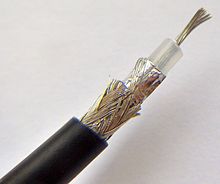
Coaxial cable, or coax, is a type of electrical cable consisting of an inner conductor surrounded by a concentric conducting shield, with the two separated by a dielectric ; many coaxial cables also have a protective outer sheath or jacket. The term coaxial refers to the inner conductor and the outer shield sharing a geometric axis.

Balanced audio is a method of interconnecting audio equipment using balanced interfaces. This type of connection is very important in sound recording and production because it allows the use of long cables while reducing susceptibility to external noise caused by electromagnetic interference. The balanced interface guarantees that induced noise appears as common-mode voltages at the receiver which can be rejected by a differential device.

<span class="mw-page-title-main">Balun</span> Electrical device

A balun is an electrical device that allows balanced and unbalanced lines to be interfaced without disturbing the impedance arrangement of either line. A balun can take many forms and may include devices that also transform impedances but need not do so. Sometimes, in the case of transformer baluns, they use magnetic coupling but need not do so. Common-mode chokes are also used as baluns and work by eliminating, rather than rejecting, common mode signals.

<span class="mw-page-title-main">Twin-lead</span> Two-conductor flat cable used to carry radio frequency signals

Twin-lead cable is a two-conductor flat cable used as a balanced transmission line to carry radio frequency (RF) signals. It is constructed of two stranded or solid copper or copper-clad steel wires, held a precise distance apart by a plastic ribbon. The uniform spacing of the wires is the key to the cable's function as a transmission line; any abrupt changes in spacing would reflect some of the signal back toward the source. The plastic also covers and insulates the wires. It is available with several different values of characteristic impedance, the most common type is 300 ohm.

In an electrical system, a ground loop or earth loop occurs when two points of a circuit are intended to have the same ground reference potential but instead have a different potential between them. This is typically caused when enough current is flowing in the connection between the two ground points to produce a voltage drop and cause two points to be at different potentials. Current may be produced in a circular ground connection by electromagnetic induction.

<span class="mw-page-title-main">Differential signalling</span> Method for electrically transmitting information

Differential signalling is a method for electrically transmitting information using two complementary signals. The technique sends the same electrical signal as a differential pair of signals, each in its own conductor. The pair of conductors can be wires in a twisted-pair or ribbon cable or traces on a printed circuit board.

<span class="mw-page-title-main">Microstrip</span> Conductor–ground plane electrical transmission line

Microstrip is a type of electrical transmission line which can be fabricated with any technology where a conductor is separated from a ground plane by a dielectric layer known as "substrate". Microstrip lines are used to convey microwave-frequency signals.

Transposition is the periodic swapping of positions of the conductors of a transmission line, in order to reduce crosstalk and otherwise improve transmission. In telecommunications this applies to balanced pairs whilst in power transmission lines three conductors are periodically transposed.

A radio transmitter or receiver is connected to an antenna which emits or receives the radio waves. The antenna feed system or antenna feed is the cable or conductor, and other associated equipment, which connects the transmitter or receiver with the antenna and makes the two devices compatible. In a radio transmitter, the transmitter generates an alternating current of radio frequency, and the feed system feeds the current to the antenna, which converts the power in the current to radio waves. In a radio receiver, the incoming radio waves excite tiny alternating currents in the antenna, and the feed system delivers this current to the receiver, which processes the signal.

<span class="mw-page-title-main">Stripline</span> Early electronic transmission line medium

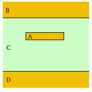
In electronics, stripline is a transverse electromagnetic (TEM) transmission line medium invented by Robert M. Barrett of the Air Force Cambridge Research Centre in the 1950s. Stripline is the earliest form of planar transmission line.

<span class="mw-page-title-main">Power dividers and directional couplers</span> Radio technology devices

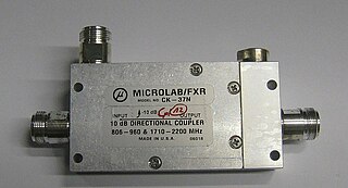
Power dividers and directional couplers are passive devices used mostly in the field of radio technology. They couple a defined amount of the electromagnetic power in a transmission line to a port enabling the signal to be used in another circuit. An essential feature of directional couplers is that they only couple power flowing in one direction. Power entering the output port is coupled to the isolated port but not to the coupled port. A directional coupler designed to split power equally between two ports is called a hybrid coupler.

<span class="mw-page-title-main">Transformer types</span> Overview of electrical transformer types

A variety of types of electrical transformer are made for different purposes. Despite their design differences, the various types employ the same basic principle as discovered in 1831 by Michael Faraday, and share several key functional parts.

<span class="mw-page-title-main">Distributed-element filter</span> Type of electronic filter circuit

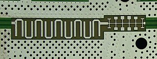
A distributed-element filter is an electronic filter in which capacitance, inductance, and resistance are not localised in discrete capacitors, inductors, and resistors as they are in conventional filters. Its purpose is to allow a range of signal frequencies to pass, but to block others. Conventional filters are constructed from inductors and capacitors, and the circuits so built are described by the lumped element model, which considers each element to be "lumped together" at one place. That model is conceptually simple, but it becomes increasingly unreliable as the frequency of the signal increases, or equivalently as the wavelength decreases. The distributed-element model applies at all frequencies, and is used in transmission-line theory; many distributed-element components are made of short lengths of transmission line. In the distributed view of circuits, the elements are distributed along the length of conductors and are inextricably mixed together. The filter design is usually concerned only with inductance and capacitance, but because of this mixing of elements they cannot be treated as separate "lumped" capacitors and inductors. There is no precise frequency above which distributed element filters must be used but they are especially associated with the microwave band.

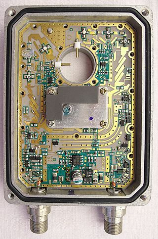
A via fence, also called a picket fence, is a structure used in planar electronic circuit technologies to improve isolation between components which would otherwise be coupled by electromagnetic fields. It consists of a row of via holes which, if spaced close enough together, form a barrier to electromagnetic wave propagation of slab modes in the substrate. Additionally if radiation in the air above the board is also to be suppressed, then a strip pad with via fence allows a shielding can to be electrically attached to the top side, but electrically behave as if it continued through the PCB.

<span class="mw-page-title-main">Planar transmission line</span> Transmission lines with flat ribbon-like conducting or dielectric lines

Planar transmission lines are transmission lines with conductors, or in some cases dielectric (insulating) strips, that are flat, ribbon-shaped lines. They are used to interconnect components on printed circuits and integrated circuits working at microwave frequencies because the planar type fits in well with the manufacturing methods for these components. Transmission lines are more than simply interconnections. With simple interconnections, the propagation of the electromagnetic wave along the wire is fast enough to be considered instantaneous, and the voltages at each end of the wire can be considered identical. If the wire is longer than a large fraction of a wavelength, these assumptions are no longer true and transmission line theory must be used instead. With transmission lines, the geometry of the line is precisely controlled so that its electrical behaviour is highly predictable. At lower frequencies, these considerations are only necessary for the cables connecting different pieces of equipment, but at microwave frequencies the distance at which transmission line theory becomes necessary is measured in millimetres. Hence, transmission lines are needed within circuits.

Air stripline is a form of electrical planar transmission line whereby a conductor in the form of a thin metal strip is suspended between two ground planes. The idea is to make the dielectric essentially air. Mechanical support of the line may be a thin substrate, periodical insulated supports, or the device connectors and other electrical items.

<span class="mw-page-title-main">Distributed-element circuit</span> Electrical circuits composed of lengths of transmission lines or other distributed components

Distributed-element circuits are electrical circuits composed of lengths of transmission lines or other distributed components. These circuits perform the same functions as conventional circuits composed of passive components, such as capacitors, inductors, and transformers. They are used mostly at microwave frequencies, where conventional components are difficult to implement.

<span class="mw-page-title-main">Earth-return telegraph</span> Telegraphy transmission method

Earth-return telegraph is the system whereby the return path for the electric current of a telegraph circuit is provided by connection to the earth through an earth electrode. Using earth return saves a great deal of money on installation costs since it halves the amount of wire that is required, with a corresponding saving on the labour required to string it. The benefits of doing this were not immediately noticed by telegraph pioneers, but it rapidly became the norm after the first earth-return telegraph was put into service by Carl August von Steinheil in 1838.

References

  1. Huurdeman, p. 54
  2. Huurdeman, p. 67

Bibliography