Shielded cable

Last updated
Four-conductor shielded cable with metal foil shield and drain wire. Shielded wire 4F.jpg
Four-conductor shielded cable with metal foil shield and drain wire.
Coaxial cable. Coaxial cable cutaway.svg
Coaxial cable.
Electronic symbol for a shielded wire ShieldedWireSymbol.png
Electronic symbol for a shielded wire

A shielded cable or screened cable is an electrical cable that has a common conductive layer around its conductors for electromagnetic shielding. [1] This shield is usually covered by an outermost layer of the cable. Common types of cable shielding can most broadly be categorized as foil type (often utilizing a metallised film), contraspiralling wire strands (braided or unbraided) or both. [2] A longitudinal wire may be necessary with dielectric spiral foils to short out each turn. [1]

Contents

The shield acts as a Faraday cage – a surface that reflects electromagnetic radiation. This reduces both the interference from outside noise onto the signals and the signals from radiating out and potentially disturbing other devices (see electromagnetic compatibility). To be effective against electric fields (see also capacitive coupling), the shield must be grounded. [3] The shield should be electrically continuous to maximize effectiveness, including any cable splices. For high frequency signals (above a few megahertz), this extends to connectors and enclosures, also circumferentially: The cable shielding needs to be circumferentially connected to the enclosure, if any, through the connector or cable gland. [1] [4] [5]

Some types of shielded cable use the shield as the return path for the signal. As contrasting examples, coaxial cable does, whereas twinax cable does not.

High voltage power cables with solid insulation are shielded to protect the cable insulation, people and equipment.

Types

Different types of shielded cables are used based on the specific requirements of the application.

Foil

Foil shielded cables use a thin layer of aluminum foil for protection. They offer reasonable flexibility and are suitable for a wide range of applications. This type of shielding is often the most effective option for blocking EMI [6]

Braided

Braided shielded cables have a wire mesh surrounding the internal wiring, offering robust protection against mechanical stress. They are more durable but less effective in preventing EMI compared to foil shields.

Combination

Combination shielded cables provide the durability of braided cables and the added protection against high levels of EMI. They are, however, heavier and less flexible than other types.

Spiral

Spiral shielding uses helically-wrapped metal strands to cover the cable’s conductors, offering good flexibility and coverage. However, they may not offer the same level of mechanical protection as braided shielding. [7]

Serve

Serve shields, or served wire shields, consist of individual wires wrapped around the cable core. They provide good flexibility and ease of termination, suitable for applications requiring frequent cable movement. [8]

Tape

Tape shields involve wrapping a conductive tape, often made of copper, around the cable. This type of shielding is used in high-voltage power cables to prevent electrical interference.

Screen

Screen shields are similar to foil shields but often use a woven screen mesh to provide additional protection. They are commonly used in high-frequency applications where both EMI shielding and physical durability are required. [9]

Applications

The use of shielded cables in security systems provides some protection from power frequency and radio frequency interference, reducing the number of false alarms being generated. The best practice is to keep data or signal cables physically separated by at least 3 inches (75mm) from 'heavy' power circuits which are in parallel.

Analog signal cable used in professional audio applications is usually shielded twisted pair cable terminated in XLR connectors. The twisted pair carries the signal in a balanced audio configuration. The audio multicore cable laid from the stage to the mixing console is also shielded.

Consumers use screened copper wire with one central conductor in an unbalanced configuration.

In signal cables

The best way to wire shielded cables for screening is to ground the shield at both ends of the cable. [10] Traditionally there existed a rule of thumb to ground only the source end of the shield to avoid ground loops. Best practice is to ground at both ends, but there is a possibility of ground loops. In airplanes, special cable is used with both an outer shield to protect against lightning and an inner shield grounded at one end to eliminate hum from the 400 Hz power system. [11]

In power cables

Medium and high-voltage power cables, in circuits over 2000 volts, usually have a shield layer of copper or aluminium tape or conducting polymer. If an unshielded insulated cable is in contact with earth or a grounded object, the electrostatic field around the conductor will be concentrated at the contact point, resulting in corona discharge, and eventual destruction of the insulation. Leakage current and capacitive current through the insulation presents a danger of electrical shock. The grounded shield equalizes electrical stress around the conductor, diverts any leakage current to ground. Stress relief cones should be applied at the shield ends, especially for cables operating at more than 2 kV to earth.

Shields on power cables may be connected to earth ground at each shield end and at splices for redundancy to prevent shock even though induced current will flow in the shield. This current will produce losses and heating and will reduce the maximum current rating of the circuit. Tests show that having a bare grounding conductor adjacent to the insulated wires will conduct the fault current to earth more quickly. On high-current circuits the shields might be connected only at one end. On very long high-voltage circuits, the shield may be broken into several sections since a long shield run may rise to dangerous voltages during a circuit fault. There is a risk of shock hazard from having only one end of the shield grounded. The maximum recommended shield potential rise is 25 volts.[ citation needed ] IEEE 422 and 525 lists the cable lengths that would limit shield potential to 25 volts for a single point ground application. [12] [13] [14]

Size ConductorOne Cable per Duct (ft)Three Cables per Duct (ft)
1/0 AWG 12504500
2/0 AWG11103970
4/0 AWG8653000
250 kcmil8152730
350 kcmil7102260
400 kcmil6552100
500 kcmil5801870
750 kcmil5101500
1000 kcmil450-
2000 kcmil340-

See also

Related Research Articles

<span class="mw-page-title-main">Wire</span> Single, usually cylindrical, flexible strand or bar or rod of metal

A wire is a flexible, round, bar of metal.

In telecommunications and professional audio, a balanced line or balanced signal pair is an electrical circuit consisting of two conductors of the same type, both of which have equal impedances along their lengths, to ground, and to other circuits. The primary advantage of the balanced line format is good rejection of common-mode noise and interference when fed to a differential device such as a transformer or differential amplifier.

<span class="mw-page-title-main">Electromagnetic compatibility</span> Electrical engineering concept

Electromagnetic compatibility (EMC) is the ability of electrical equipment and systems to function acceptably in their electromagnetic environment, by limiting the unintentional generation, propagation and reception of electromagnetic energy which may cause unwanted effects such as electromagnetic interference (EMI) or even physical damage to operational equipment. The goal of EMC is the correct operation of different equipment in a common electromagnetic environment. It is also the name given to the associated branch of electrical engineering.

<span class="mw-page-title-main">Ground (electricity)</span> Reference point in an electrical circuit from which voltages are measured

In electrical engineering, ground or earth may be a reference point in an electrical circuit from which voltages are measured, a common return path for electric current, or a direct physical connection to the Earth.

<span class="mw-page-title-main">Electrical cable</span> Assembly of one or more wires running side by side or bundled

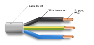
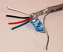
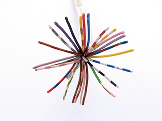
An electrical cable is an assembly of one or more wires running side by side or bundled, which is used as an electrical conductor, i.e., to carry electric current. One or more electrical cables and their corresponding connectors may be formed into a cable assembly, which is not necessarily suitable for connecting two devices but can be a partial product. Cable assemblies can also take the form of a cable tree or cable harness, used to connect many terminals together.

<span class="mw-page-title-main">Coaxial cable</span> Electrical cable type with concentric inner conductor, insulator, and conducting shield

Coaxial cable, or coax, is a type of electrical cable consisting of an inner conductor surrounded by a concentric conducting shield, with the two separated by a dielectric ; many coaxial cables also have a protective outer sheath or jacket. The term coaxial refers to the inner conductor and the outer shield sharing a geometric axis.

<span class="mw-page-title-main">Twisted pair</span> Type of wiring used for communications

Twisted pair cabling is a type of communications cable in which two conductors of a single circuit are twisted together for the purposes of improving electromagnetic compatibility. Compared to a single conductor or an untwisted balanced pair, a twisted pair reduces electromagnetic radiation from the pair and crosstalk between neighbouring pairs and improves rejection of external electromagnetic interference. It was invented by Alexander Graham Bell.

<span class="mw-page-title-main">Faraday cage</span> Enclosure of conductive mesh used to block electric fields

A Faraday cage or Faraday shield is an enclosure used to block some electromagnetic fields. A Faraday shield may be formed by a continuous covering of conductive material, or in the case of a Faraday cage, by a mesh of such materials. Faraday cages are named after scientist Michael Faraday, who first constructed one in 1836.

Balanced audio is a method of interconnecting audio equipment using balanced interfaces. This type of connection is very important in sound recording and production because it allows the use of long cables while reducing susceptibility to external noise caused by electromagnetic interference. The balanced interface guarantees that induced noise appears as common-mode voltages at the receiver which can be rejected by a differential device.

Electrical wiring in North America follows the regulations and standards applicable at the installation location. It is also designed to provide proper function, and is also influenced by history and traditions of the location installation.

In an electrical system, a ground loop or earth loop occurs when two points of a circuit are intended to have the same ground reference potential but instead have a different potential between them. This is typically caused when enough current is flowing in the connection between the two ground points to produce a voltage drop and cause two points to be at different potentials. Current may be produced in a circular ground connection by electromagnetic induction.

<span class="mw-page-title-main">Electrical wiring</span> Electrical installation of cabling

Electrical wiring is an electrical installation of cabling and associated devices such as switches, distribution boards, sockets, and light fittings in a structure.

<span class="mw-page-title-main">Differential signalling</span> Method for electrically transmitting information

Differential signalling is a method for electrically transmitting information using two complementary signals. The technique sends the same electrical signal as a differential pair of signals, each in its own conductor. The pair of conductors can be wires in a twisted-pair or ribbon cable or traces on a printed circuit board.

<span class="mw-page-title-main">Power cable</span> Bundle of wires for transmitting electricity

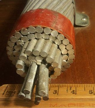
A power cable is an electrical cable, an assembly of one or more electrical conductors, usually held together with an overall sheath. The assembly is used for transmission of electrical power. Power cables may be installed as permanent wiring within buildings, buried in the ground, run overhead, or exposed. Power cables that are bundled inside thermoplastic sheathing and that are intended to be run inside a building are known as NM-B.

An earthing system or grounding system (US) connects specific parts of an electric power system with the ground, typically the Earth's conductive surface, for safety and functional purposes. The choice of earthing system can affect the safety and electromagnetic compatibility of the installation. Regulations for earthing systems vary among countries, though most follow the recommendations of the International Electrotechnical Commission (IEC). Regulations may identify special cases for earthing in mines, in patient care areas, or in hazardous areas of industrial plants.

<span class="mw-page-title-main">Unbalanced line</span>

In telecommunications and electrical engineering in general, an unbalanced line is a pair of conductors intended to carry electrical signals, which have unequal impedances along their lengths and to ground and other circuits. Examples of unbalanced lines are coaxial cable or the historic earth return system invented for the telegraph, but rarely used today. Unbalanced lines are to be contrasted with balanced lines, such as twin-lead or twisted pair which use two identical conductors to maintain impedance balance throughout the line. Balanced and unbalanced lines can be interfaced using a device called a balun.

A radio transmitter or receiver is connected to an antenna which emits or receives the radio waves. The antenna feed system or antenna feed is the cable or conductor, and other associated equipment, which connects the transmitter or receiver with the antenna and makes the two devices compatible. In a radio transmitter, the transmitter generates an alternating current of radio frequency, and the feed system feeds the current to the antenna, which converts the power in the current to radio waves. In a radio receiver, the incoming radio waves excite tiny alternating currents in the antenna, and the feed system delivers this current to the receiver, which processes the signal.

<span class="mw-page-title-main">Transformer types</span> Overview of electrical transformer types

A variety of types of electrical transformer are made for different purposes. Despite their design differences, the various types employ the same basic principle as discovered in 1831 by Michael Faraday, and share several key functional parts.

<span class="mw-page-title-main">High-voltage cable</span> Cable used for electric power transmission at high voltage

A high-voltage cable is a cable used for electric power transmission at high voltage. A cable includes a conductor and insulation. Cables are considered to be fully insulated. This means that they have a fully rated insulation system that will consist of insulation, semi-con layers, and a metallic shield. This is in contrast to an overhead line, which may include insulation but not fully rated for operating voltage. High-voltage cables of differing types have a variety of applications in instruments, ignition systems, and alternating current (AC) and direct current (DC) power transmission. In all applications, the insulation of the cable must not deteriorate due to the high-voltage stress, ozone produced by electric discharges in air, or tracking. The cable system must prevent contact of the high-voltage conductor with other objects or persons, and must contain and control leakage current. Cable joints and terminals must be designed to control the high-voltage stress to prevent the breakdown of the insulation.

Physical media refers to the physical materials that are used to store or transmit information in data communications. These physical media are generally physical objects made of materials such as copper or glass. They can be touched and felt, and have physical properties such as weight and color. For a number of years, copper and glass were the only media used in computer networking.

References

  1. 1 2 3 "EMC techniques in electronic design Part 2 - Cables and Connectors" (PDF). May 2009. Retrieved 2022-04-18. For good shielding performance, the electrical bonding between a cable's shield and the shields of its connectors or glands and any shielded enclosures should have no gaps in it either. This means that there should be a seamless low-impedance electrical connection all around the perimeter or circumference of the electrical joint. This is often referred to as 360° shield bonding (even when the connector or gland isn't circular), and it applies between a cable shield and connector shield, the shields of two mating connectors and between the shield of a connector and the metal chassis or structure it is mounted on.
  2. "Popular Shielding Types". 2021. Retrieved 2022-04-18.
  3. "Shield Grounding" . Retrieved 2019-02-28.
  4. "Introduction to electromagnetic compatibility" (PDF). Analog Devices. May 2009. Retrieved 2022-04-18. In summary, for protection against low-frequency (<1 MHz) electric-field interference, grounding the shield at one end is acceptable. For high-frequency interference (>1 MHz), the preferred method is grounding the shield at both ends, using 360° circumferential bonds between the shield and the connector, and maintaining metal-to-metal continuity between the connectors and the enclosure.
  5. "Effectiveness of Shield Termination Techniques Tested with TEM Cell and Bulk Current Injection" (PDF). NASA. 2009. Retrieved 2022-04-18. Although it has long been known that pigtail shield connections underperform 360° termination methods, our experiments indicated that pigtails were typically worse by more than 35 dB for frequencies above a few MHz.
  6. . "Shielded vs. Unshielded Cables". WesBell Electronics. February 8, 2024.
  7. "Understanding Shielded Cables: An In-Depth Guide". Electricity Magnetism. October 26, 2023.
  8. "A Preliminary Guide of Shielded Cables". ZGSM WIRE HARNESS.
  9. "Understanding Shielded Cables: An In-Depth Guide". Electricity Magnetism. October 26, 2023.
  10. "Bonding Cable Shields at Both Ends to Avoid Noise".
  11. "Aero 10 - Loop Resistance Tester". 090528 boeing.com
  12. Thomas P. Arnold; C. David Mercier (1997). Southwire Company Power Cable Manual (2 ed.). Carrollton, GA: Southwire Company.
  13. IEEE 422: IEEE Guide for the Design and Installation of Cable Systems in Power Generating Stations
  14. IEEE 525: IEEE Guide for the Design and Installation of Cable Systems in Substations