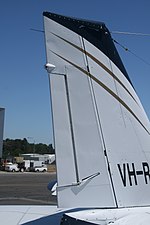
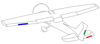
The vertical stabilizer is the fixed vertical surface of the empennage
A vertical stabilizer or tail fin[1][2] is the static part of the vertical tail of an aircraft.[1] The term is commonly applied to the assembly of both this fixed surface and one or more movable rudders hinged to it. Their role is to provide control, stability and trim in yaw (also known as directional or weathercock stability). It is part of the aircraft empennage, specifically of its stabilizers.
The vertical tail[3] is typically mounted on top of the rear fuselage, with the horizontal stabilizers mounted on the side of the fuselage (a configuration termed "conventional tail"). Other configurations, such as T-tail or twin tail, are sometimes used instead.
Control surfaces at the tail of a conventional aircraft
The vertical tail of an aircraft typically consists of a fixed vertical stabilizer or fin on which a movable rudder is mounted. A trim tab may similarly be mounted on the rudder. Together, their role is to enable trim in the yaw direction (compensate moments in yaw generated by any asymmetry in thrust or drag), enable the aircraft to be controlled in yaw (for example, to initiate side slip during a crosswind landing), as well as provide stability in yaw (weathercock or directional stability).[4]
The greater its position away from the center of gravity, the more effective the vertical tail can be. Thus, shorter aircraft typically feature larger vertical tails; for example, the vertical tail of the short Airbus A318 is larger than that of its longer counterparts in the A320 family.
The effectiveness of the vertical tail depends on its efficiency and the vertical tail volume coefficient[5] (also called volume ratio[6]), which non-dimensionalizes its area and arm with the dimensions of the main wing:
(where the indices v and w stand for vertical tail and wing respectively, S stands for area, and L_w is typically the mean aerodynamic chord). Values for the vertical tail coefficient vary only mildly from aircraft one type of aircraft to another, with extreme values ranging from 0.02 (sailplane) to 0.09 (jet aircraft transport).[5]
The tail efficiency is the ratio of the dynamic pressure at the tail to that in the freestream. The tail has its maximum capability when immersed in the free stream with an efficiency of one. When partially immersed in a wake its effectiveness is reduced because the wake has a lower dynamic pressure than the free stream. The fin height may need to be increased to restore its required effectiveness in certain flight conditions. The Panavia Tornado had a tall fin for directional stability at high angles of incidence.[7]
Trim and control in yaw
The rudder is the directional control surface and is usually hinged to the fin or vertical stabilizer. Moving it allows the pilot to control yaw about the vertical axis, i.e., change the horizontal direction in which the nose is pointing.
Maximum rudder deflection is usually controlled by a rudder travel limiter. The largest achievable angle of a rudder at a particular flight condition is called its blowdown limit. It represents a balance between the aerodynamic forces on the rudder and the mechanical forces from the actuating mechanism.[8]
Multi-engined aircraft, especially those with wing-mounted engines, have large powerful rudders. They are required to provide sufficient control after an engine failure on take-off at maximum weight and cross wind limit[9] and cross-wind capability on normal take-off and landing.[10]
For taxiing and during the beginning of the take-off, aircraft are steered by a combination of rudder input as well as turning the nosewheel or tailwheel. At slow speeds the nosewheel or tailwheel has the most control authority, but as the speed increases the aerodynamic effects of the rudder increases, thereby making the rudder more and more important for yaw control. In some aircraft (mainly small aircraft) both of these mechanisms are controlled by the rudder pedals so there is no difference to the pilot. In other aircraft there is a special tiller controlling the wheel steering and the pedals control the rudder, and a limited amount of wheel steering (usually 5 degrees of nosewheel steering). For these aircraft the pilots stop using the tiller after lining up with the runway prior to take-off, and begin using it after landing before turning off the runway, to prevent over correcting with the sensitive tiller at high speeds. The pedals may also be used for small corrections while taxiing in a straight line, or leading in or out of a turn, before applying the tiller, to keep the turn smooth.[citation needed]
With the controls in the neutral position, a plane may still gently yaw to one side. This is corrected through the setting of a trim surface, often a separate trim tab mounted on the rudder but sometimes the rudder itself, to counteract the yaw and ensure the plane flies in a straight line.[citation needed]
Changing the setting of a trim tab adjusts the neutral or resting position of a control surface (such as an elevator or rudder). As the desired position of a control surface changes (corresponding mainly to different speeds), an adjustable trim tab will allow the operator to reduce the manual force required to maintain that position—to zero, if used correctly. Thus the trim tab acts as a servo tab. Because the center of pressure of the trim tab is further away from the axis of rotation of the control surface than the center of pressure of the control surface, the movement generated by the tab can match the movement generated by the control surface. The position of the control surface on its axis will change until the torque from the control surface and the trim surface balance each other.[citation needed]
Movement caused by the use of rudder
The rudder is controlled through rudder pedals on the bottom rear of the yoke in this photo of a Boeing 727 cockpit.
The water rudders on this Cessna 208 Caravanfloatplane are the small vertical surfaces on the rear end of each float. Their setting is controlled from the cockpit.
Yaw stability
The vertical tail plays a determining role in yaw stability, providing most of the required restoring moment about the center of gravity when the aircraft slips. Yaw stability is typically quantified using the derivative of moment coefficient with respect to yaw angle.[6]
The airflow over the vertical tail is often influenced by the fuselage, wings and engines of the aircraft, both in magnitude and direction.[6] The main wing and the horizontal stabilizer, if they are highly swept, can contribute significantly to the yaw stability; wings swept backwards tend to increase yaw stability. Sweep in the wing and horizontal tail of a conventional airplane, however, does not affect airplane trim in yaw.[6]
Dihedral in the main wing and horizontal tail can also have a small effect on the static yaw stability. This effect is complex and coupled with the effect of wing sweep and flow about the fuselage.[6]
Propellers, especially when they are advancing so that their axis makes an angle to the freestream velocity, can affect the static stability of an airplane in yaw.[6]
Coupling with roll
The vertical tail affects the behavior of the aircraft in roll, since its aerodynamic center typically lies far above the center of gravity of the aircraft.[1] When the aircraft slips to the right, the relative wind and side force on the vertical tail translate into an anti-clockwise moment in roll.[6]
Supersonic flight
Dual ventral fins on an F-16
In supersonic flight, the vertical tail becomes progressively less effective with increasing Mach number until the loss of stability may no longer be acceptable.[11] The stability is reduced because the lift, or side force, generated by the tail reduces with speed for each degree of sideslip angle (lift-curve slope). This results from the very different pressure distribution, with shock waves and expansion waves, compared to subsonic.[12] To achieve the required stability at the maximum operating speed of the aircraft the vertical tail may be enlarged, such as on the North American F-100 Super Sabre (the initial fin area requirement was underestimated). Extra area may be added by installing ventral fins (such as on higher-speed, later versions of the Vought F-8 Crusader), or folding-down wingtips (such as on the North American XB-70 Valkyrie). If a bigger tail is not acceptable automatic rudder deflections may be used to increase the tail side force and restore directional stability. This method was used on the Avro Arrow.[13]
Stall of the vertical tail
A dorsal fin is visible at the base of the vertical tail of this Boeing 737-300
The vertical tail sometimes features a fillet or dorsal fin at its forward base, which helps to increase the stall angle of the vertical surface (resulting in vortex lift), and in this way prevent a phenomenon called rudder lock or rudder reversal. Rudder lock occurs when the force on a deflected rudder (e.g. in a steady sideslip) suddenly reverses as the vertical tail stalls. This may leave the rudder stuck at full deflection with the pilot unable to recenter it.[14] The dorsal fin was introduced in the 1940s, for example on the 1942 Douglas DC-4, predating the wing strakes of the fighter aircraft developed in the 1970s, such as the F-16.[15]
Structural considerations
The rudder and fin on a large, or fast, aircraft are each subject to a considerable force which increases with rudder deflection. An extreme case occurs with a departure from controlled flight, known as an upset, which in the context of fin and rudder is excessive sideslip. For large transport aircraft the stabilizing moment necessary for recovery comes from the fin with little requirement for rudder deflection. These aircraft do not have a requirement to withstand near-full rudder deflections in these circumstances[16] because the structural weight required to prevent structural failure would make them commercially unviable. Loss of the complete fin and rudder assembly occurred on American Airlines Flight 587 when the pilots used full rudder deflections while following in the wake of a very large jet.[17]
Clear air turbulence caused the failure of the complete fin and rudder assembly on a Boeing B-52 Stratofortress after which the pilots made a successful landing. B-52 bombers instrumented for gust and manoeuvre loads recorded gusts from clear air turbulence considerably more than the design limit with highest loads at 34,000 feet.[18]
The English Electric Lightning T4 prototype fin failure was caused by inertial roll coupling while doing high-rate rolls. The fin was enlarged, strengthened and roll-rate limitations were imposed. However, the first T5 also had a fin failure while doing rapid rolling trials with rocket pack extended.[19]
A Lightning lost its fin due to interaction between aircraft in close proximity at low level when flying in formation at M 0.97, an aerobatic display routine. Limitations were imposed including separation between aircraft when in formation.[19]
Fin buffeting is a critical issue for fighter aircraft with twin or single fins because the fatigue life of the fin structure is reduced by the fluctuating loads caused by burst vortices impinging on the fin. The single fin on the Eurofighter Typhoon experiences buffet loads caused by burst vortices which originate from the canard and wing leading edges at high angles of attack. The sides of the top-mounted airbrake, when deflected, also shed vortices which impinge, after bursting, on the fin. Buffeting from the extended airbrake is highest when the airbrake effective angle of attack is greatest, which for a fully-extended airbrake is greatest at low aircraft angle of attack and least when manoeuvring.[20] The McDonnell Douglas F/A-18 Hornet twin fins are subject to buffeting from the breakdown or bursting of the leading-edge extension (LEX) vortex in front of the tail.[21] The addition of a LEX fence significantly reduces the buffeting and increases fin fatigue life.[22]
B-52H (AF Ser. No. 61-0023), instrumented to measure gust loads to investigate structural failures, still flying after its vertical stabilizer was lost in severe turbulence on 10 January 1964. The aircraft landed safely.[23]
F/A-18C showing LEX fence which reduces fin buffeting
Typhoon showing extended airbrake which causes significant fin buffet
The Lockheed SR-71 Blackbird and North American X-15 used fixed stubs for the fins and rudders for the remaining height. Conventional rudders would have been inadequate for the SR-71 because excessive deflections would have been required for the engine-out case causing unacceptable trim drag.[26] Early configurations put forward for the X-15 show a conventional fixed fin and trailing rudder, and a ventral fin. This was changed to dorsal and ventral fins each with the outer half acting as a rudder.[27]
North American X-15 showing full-chord rudders on fixed dorsal and ventral stabilizers
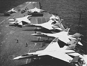
Twin tail aircraft have two vertical stabilizers. Many modern combat aircraft use this configuration. The twin rudders may be used in the gear-down configuration for additional longitudinal control with toe-in or flare-out (McDonnell Douglas F/A-18 Hornet[28]). Twin rudders are also used as an airbrake as in the case of the Lockheed Martin F-22 Raptor which uses differential rudder, together with other control surface deflections, for speed control as it has no dedicated airbrake.[29]
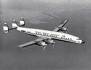
A variation on the twin tail, the triple tail has three vertical stabilizers. The WW II era Avro Manchester was given a third fin when the original twin fin proved insufficient. The Lockheed Constellation used three fins to give the airplane the required vertical stabilizer area while at the same time keeping the overall height low enough so that it could fit into hangars for maintenance.
A V-tail has no distinct vertical or horizontal stabilizers. Rather, they are merged into control surfaces known as ruddervators which control both pitch and yaw. The arrangement looks like the letter V, and is also known as a "butterfly tail". The Beechcraft Bonanza Model 35 uses this configuration, as does the Lockheed F-117 Nighthawk.
An unusual cruciform design is used on the Lockheed Jetstar. For longitudinal trim the entire tail assembly pivots up and down through 10 degrees about an attachment point at the bottom of the fin rear spar.[30][31]
Lockheed Jetstar. Evidence of its pivoting fin can be seen in the diagonal line below the horizontal stabilizer
Folding for storage
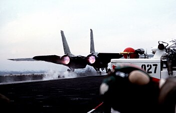
The top part of the vertical fin on the North American A-5 Vigilante folds to the side due to the hangar deck height restriction.
Devices similar to vertical tails have been used on cars such as the 1955 Jaguar D-type or the 2013 Lamborghini Veneno. On race cars, its primary purpose is to reduce sudden high-speed yaw-induced blow-overs that would cause cars to flip due to lift when subject to extreme yaw angles during cornering or in a spin.[citation needed] Since 2011, the vertical stabilizer has become mandatory for all newly homologated Le Mans Prototypes.[32]
Some Formula 1 teams utilized a vertical stabilizer as a way to disrupt the airflow to the rear wing reducing drag, the most radical system being the "F-duct" found in the 2010 McLaren MP4-25 and Ferrari F10. On demand by the driver, this system diverted air from a duct in the front of the car through a tunnel in the vertical fin onto the rear wing to stall it and reduce drag on the straights on which downforce was not needed.[citation needed] The system was banned for the 2011 Formula 1 season.[citation needed]
Ferrari F10 with vertical fin between air inlet and wing
Boeing 737 rudder issues – Series of accidents and incidents involving the rudder of the Boeing 737 jamming and causing the aircraft to uncontrollably roll
Related Research Articles
A tailplane, also known as a horizontal stabiliser, is a small lifting surface located on the tail (empennage) behind the main lifting surfaces of a fixed-wing aircraft as well as other non-fixed-wing aircraft such as helicopters and gyroplanes. Not all fixed-wing aircraft have tailplanes. Canards, tailless and flying wing aircraft have no separate tailplane, while in V-tail aircraft the vertical stabiliser, rudder, and the tail-plane and elevator are combined to form two diagonal surfaces in a V layout.
An aileron is a hinged flight control surface usually forming part of the trailing edge of each wing of a fixed-wing aircraft. Ailerons are used in pairs to control the aircraft in roll, which normally results in a change in flight path due to the tilting of the lift vector. Movement around this axis is called 'rolling' or 'banking'.
A T-tail is an empennage configuration in which the tailplane is mounted to the top of the fin. The arrangement looks like the capital letter T, hence the name. The T-tail differs from the standard configuration in which the tailplane is mounted to the fuselage at the base of the fin.
Aircraft flight control surfaces are aerodynamic devices allowing a pilot to adjust and control the aircraft's flight attitude.
In aeronautics, dihedral is the angle between the left and right wings of an aircraft. "Dihedral" is also used to describe the effect of sideslip on the rolling of the aircraft.
The V-tail or vee-tail of an aircraft is an unconventional arrangement of the tail control surfaces that replaces the traditional vertical and horizontal surfaces with two surfaces set in a V-shaped configuration. It is not widely used in aircraft design. The aft edge of each twin surface is a hinged control surface called a ruddervator, which combines the functions of both a rudder and elevator.
In aviation, an aircraft is said to have relaxed stability if it has low or negative stability.
Elevators are flight control surfaces, usually at the rear of an aircraft, which control the aircraft's pitch, and therefore the angle of attack and the lift of the wing. The elevators are usually hinged to the tailplane or horizontal stabilizer. They may be the only pitch control surface present, and are sometimes located at the front of the aircraft or integrated into a rear "all-moving tailplane", also called a slab elevator or stabilator.
A stabilator is a fully movable aircraft horizontal stabilizer. It serves the usual functions of longitudinal stability, control and stick force requirements otherwise performed by the separate parts of a conventional horizontal stabilizer and elevator. Apart from reduced drag, particularly at high Mach numbers, it is a useful device for changing the aircraft balance within wide limits, and for reducing stick forces.
The empennage, also known as the tail or tail assembly, is a structure at the rear of an aircraft that provides stability during flight, in a way similar to the feathers on an arrow. The term derives from the French language verb empenner which means "to feather an arrow". Most aircraft feature an empennage incorporating vertical and horizontal stabilising surfaces which stabilise the flight dynamics of yaw and pitch, as well as housing control surfaces.
Aircraft flight mechanics are relevant to fixed wing and rotary wing (helicopters) aircraft. An aeroplane, is defined in ICAO Document 9110 as, "a power-driven heavier than air aircraft, deriving its lift chiefly from aerodynamic reactions on surface which remain fixed under given conditions of flight".
The United States Air Force Stability and Control Digital DATCOM is a computer program that implements the methods contained in the USAF Stability and Control DATCOM to calculate the static stability, control and dynamic derivative characteristics of fixed-wing aircraft. Digital DATCOM requires an input file containing a geometric description of an aircraft, and outputs its corresponding dimensionless stability derivatives according to the specified flight conditions. The values obtained can be used to calculate meaningful aspects of flight dynamics.
Trim tabs are small surfaces connected to the trailing edge of a larger control surface on a boat or aircraft, used to control the trim of the controls, i.e. to counteract hydro- or aerodynamic forces and stabilise the boat or aircraft in a particular desired attitude without the need for the operator to constantly apply a control force. This is done by adjusting the angle of the tab relative to the larger surface.
The critical engine of a multi-engine fixed-wing aircraft is the engine that, in the event of failure, would most adversely affect the performance or handling abilities of an aircraft. On propeller aircraft, there is a difference in the remaining yawing moments after failure of the left or the right (outboard) engine when all propellers rotate in the same direction due to the P-factor. On turbojet and turbofan twin-engine aircraft, there usually is no difference between the yawing moments after failure of a left or right engine in no-wind condition.
A twin tail is a type of vertical stabilizer arrangement found on the empennage of some aircraft. Two vertical stabilizers—often smaller on their own than a single conventional tail would be—are mounted at the outside of the aircraft's horizontal stabilizer. This arrangement is also known as an H-tail, as it resembles a capital "H" when viewed from the rear. The twin tail was used on a wide variety of World War II multi-engine designs that saw mass production, especially on the American B-24 Liberator and B-25 Mitchell bombers, the British Avro Lancaster and Handley Page Halifax heavy bombers, and the Soviet Union's Petlyakov Pe-2 attack bomber.
An aircraft stabilizer is an aerodynamic surface, typically including one or more movable control surfaces, that provides longitudinal (pitch) and/or directional (yaw) stability and control. A stabilizer can feature a fixed or adjustable structure on which any movable control surfaces are hinged, or it can itself be a fully movable surface such as a stabilator. Depending on the context, "stabilizer" may sometimes describe only the front part of the overall surface.
The dynamic stability of an aircraft refers to how the aircraft behaves after it has been disturbed following steady non-oscillating flight.
In aeronautics, a canard is a wing configuration in which a small forewing or foreplane is placed forward of the main wing of a fixed-wing aircraft or a weapon. The term "canard" may be used to describe the aircraft itself, the wing configuration, or the foreplane. Canard wings are also extensively used in guided missiles and smart bombs.
In aeronautics, a tailless aircraft is an aircraft with no other horizontal aerodynamic surface besides its main wing. It may still have a fuselage, vertical tail fin, and/or vertical rudder.
In flight dynamics, longitudinal stability is the stability of an aircraft in the longitudinal, or pitching, plane. This characteristic is important in determining whether an aircraft pilot will be able to control the aircraft in the pitching plane without requiring excessive attention or excessive strength.
1 2 Raymer, Daniel P. (1999). Aircraft Design: A Conceptual Approach (3rded.). Reston, Virginia: American Institute of Aeronautics and Astronautics. ISBN1563472813.
1 2 3 4 5 6 7 Phillips, Warren F. (2010). Mechanics of Flight (2nded.). Hoboken, New Jersey: Wiley & Sons. ISBN9780470539750.
↑ Fin Design For Combat Aircraft Fundamentals Of Design - V,Air International magazine,January 1980,p.22
↑ Aerodynamics For Naval Aviators,H.H.Hurt Jr.,Revised January 1965,NAVWEPS 00-80T-80,Issued By The Office Of The Chief Of Naval Operations Aviation Training Division,p.287
↑ Fundamentals Of Design-V Fin Design For Combat Aircraft,B R A Burns,Air International magazine,January 1980,p.23
↑ Erripis, Loannis K. (December 13, 2010). "The New Audi R18 LMP1". Robotpig.net. Archived from the original on August 26, 2011. Retrieved March 30, 2011.
This page is based on this Wikipedia article Text is available under the CC BY-SA 4.0 license; additional terms may apply. Images, videos and audio are available under their respective licenses.