Wheel arrangement

Last updated
Locomotives of different types (Whyte and UIC wheel notation) Locotypes mod.gif
Locomotives of different types (Whyte and UIC wheel notation)

In rail transport, a wheel arrangement or wheel configuration is a system of classifying the way in which wheels are distributed under a locomotive. [1] Several notations exist to describe the wheel assemblies of a locomotive by type, position, and connections, with the adopted notations varying by country. Within a given country, different notations may also be employed for different kinds of locomotives, such as steam, electric, and diesel powered.

Contents

Especially in steam days, wheel arrangement was an important attribute of a locomotive because there were many different types of layout adopted, each wheel being optimised for a different use (often with only some being actually "driven"). Modern diesel and electric locomotives are much more uniform, usually with all axles driven.

Major notation schemes

The main notations are the Whyte notation (based on counting the wheels), the AAR wheel arrangement notation (based on counting either the axles or the bogies), and the UIC classification of locomotive axle arrangements (based on counting either the axles or the bogies).

Whyte notation is generally used for steam locomotives throughout the United States, Canada, the United Kingdom and Ireland. For diesels and electrics, North America uses the AAR wheel arrangement scheme while British practice uses a slightly simplified form of the European UIC classification scheme (except for small diesel shunters, where Whyte notation is used).

In mainland Europe, the UIC classification scheme is generally used for all locomotive types including steam, with some exceptions. In France, the UIC classification is used for diesels and electrics while a scheme similar to the Whyte notation, but counting axles instead of wheels, is used for steam locomotives. Notably, Switzerland had its own separate notation system until 1989, with the Swiss locomotive and railcar classification now only retained for its narrow gauge railways.

Comparison of wheel arrangements and wheel picture

VDEV/VMEV/UIC-systemWhyte-notationAmerican namePicture scheme
Locomotive front is to the left
A1 0-2-2 Oo
A2 0-2-4 Ooo
1A 2-2-0 PlanetoO
1A1 2-2-2 PatenteeoOo
1A2 2-2-4 oOoo
2A 4-2-0 Crampton, Norris, JervisooO
2A1 4-2-2 Single DriverooOo
2A2 4-2-4 ooOoo
3A 6-2-0 CramptonoooO
N/A 0-3-0 OOO
B 0-4-0 Four-Wheel-SwitcherOO
B1 0-4-2 OOo
B2 0-4-4 ForneyOOoo
B3 0-4-6 OOooo
1B 2-4-0 HanscomoOO
1B1 2-4-2 ColumbiaoOOo
1B2 2-4-4 oOOoo
1B3 2-4-6 oOOooo
2B 4-4-0 American, Eight-WheelerooOO
2B1 4-4-2 AtlanticooOOo
2B2 4-4-4 Jubilee (CA), Reading (US)ooOOoo
2B3 4-4-6 ooOOooo
C 0-6-0 Six-Wheel-SwitcherOOO
C1 0-6-2 OOOo
C2 0-6-4 OOOoo
1C 2-6-0 MoguloOOO
1′C1′ 2-6-2 PrairieoOOOo
1C2 2-6-4 AdriaticoOOOoo
1C3 2-6-6 oOOOooo
2C 4-6-0 Ten-WheelerooOOO
2C1 4-6-2 PacificooOOOo
2C2 4-6-4 Hudson, BalticooOOOoo
D 0-8-0 Eight-Wheel-SwitcherOOOO
D1 0-8-2 OOOOo
D2 0-8-4 OOOOoo
D3 0-8-6 OOOOooo
1D 2-8-0 ConsolidationoOOOO
1D1 2-8-2 MikadooOOOOo
1D1 2-8-2TMacArthuroOOOOo
1D2 2-8-4 BerkshireoOOOOoo
1D3 2-8-6 oOOOOooo
2D 4-8-0 Twelve-Wheeler, MastodonooOOOO
2D1 4-8-2 Mountain, Mohawk (NYC)ooOOOOo
2D2 4-8-4 Northern, General Service (SP), Golden State (SP), Niagara (NYC), WyomingooOOOOoo
2D3 4-8-6 ooOOOOooo
3D3 6-8-6 Turbine (Pennsylvania Railroad Steam Turbine)oooOOOOooo
E 0-10-0 Ten-Wheel SwitcherOOOOO
E1 0-10-2 UnionOOOOOo
1E 2-10-0 DecapodoOOOOO
2E 4-10-0 MastodonooOOOOO
1E1 2-10-2 Santa FeoOOOOOo
1E2 2-10-4 Texas, Selkirk (Canadian Pacific)oOOOOOoo
2E1 4-10-2 Southern Pacific, OverlandooOOOOOo
F 0-12-0 Pennsylvania, Twelve-Wheel-SwitcherOOOOOO
1F 2-12-0 CentipedeoOOOOOO
1F1 2-12-2 JavanicoOOOOOOo
2F1 4-12-2 Union PacificooOOOOOOo
2G2 4-14-4 ooOOOOOOOoo
Soviet (AA) 0-2-2-0 O O
BB 0-4-4-0 nameless (Mallet)OO OO
BB1 0-4-4-2 nameless (Mallet)OO OOo
2BB2 4-4-4-4 nameless (Pennsylvania Railroad Duplex)ooOO OOoo
3BB3 6-4-4-6 oooOO OOooo
2CB2 4-6-4-4 nameless (Pennsylvania Railroad Duplex)ooOOO OOoo
CC 0-6-6-0 nameless (Mallet)OOO OOO
(1C)C 2-6-6-0 nameless (Mallet)oOOO OOO
(1C)C1 2-6-6-2 nameless (Mallet)oOOO OOOo
(1C)C2 2-6-6-4 nameless (Simple articulated)oOOO OOOoo
(2C)C2 4-6-6-4 Challenger (Simple articulated)ooOOO OOOoo
(1C)C3 2-6-6-6 Allegheny, Blue Ridge (Mallet/Simple articulated)oOOO OOOooo
DD 0-8-8-0 Angus (Mallet)OOOO OOOO
(1D)D 2-8-8-0 nameless (Mallet)oOOOO OOOO
(1D)D1 2-8-8-2 nameless (Mallet)oOOOO OOOOo
(1D)D2 2-8-8-4 Yellowstone (Mallet/Simple articulated)oOOOO OOOOoo
(2D)D1 4-8-8-2 nameless (Simple articulated)ooOOOO OOOOo
(2D)D24-8-8-4 Big Boy (Simple articulated)ooOOOO OOOOoo
(1E)E1 2-10-10-2 Virginian (Mallet)oOOOOO+OOOOOo
(1D1)(1D1) 2-8-2+2-8-2 Nameless, Garratt oOOOOo+oOOOOo
(2C1)(1C2) 4-6-2+2-6-4 nameless (Garratt)ooOOOo+oOOOoo
(2C2)(2C2) 4-6-4+4-6-4 nameless (Garratt)ooOOOoo+ooOOOoo
(2D)(D2) 4-8-0+0-8-4 nameless (Garratt)ooOOOO+OOOOoo
(2D1)(1D2) 4-8-2+2-8-4 Double Mountain (Garratt)ooOOOOo+oOOOOoo
(2D2)(2D2) 4-8-4+4-8-4 nameless (Garratt)ooOOOOoo+ooOOOOoo

Geared steam locomotives

Geared steam locomotives such as Shays, Heislers, and Climaxes do not have a standard wheel arrangement classification system. Instead of being classified by wheel arrangement, they are instead classified by their design and their number of trucks.

No. of trucksAmerican namePicture scheme
2-truckClass A Shay, Class B Shay, Class A Climax, Class B Climax, Heisleroo oo
3-truckClass C Shay, Class C Climax, Heisleroo oo oo
4-truckClass D Shayoo oo oo oo

See also

Related Research Articles

<span class="mw-page-title-main">Whyte notation</span> Code for arrangement of locomotive wheels

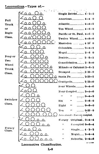
The Whyte notation is a classification method for steam locomotives, and some internal combustion locomotives and electric locomotives, by wheel arrangement. It was devised by Frederick Methvan Whyte, and came into use in the early twentieth century following a December 1900 editorial in American Engineer and Railroad Journal.

<span class="mw-page-title-main">0-4-0</span> Locomotive wheel arrangement

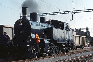
Under the Whyte notation for the classification of steam locomotives, 0-4-0 represents one of the simplest possible types, that with two axles and four coupled wheels, all of which are driven. The wheels on the earliest four-coupled locomotives were connected by a single gear wheel, but from 1825 the wheels were usually connected with coupling rods to form a single driven set.

<span class="mw-page-title-main">Driving wheel</span> Powered wheel of a locomotive

On a steam locomotive, a driving wheel is a powered wheel which is driven by the locomotive's pistons. On a conventional, non-articulated locomotive, the driving wheels are all coupled together with side rods ; normally one pair is directly driven by the main rod which is connected to the end of the piston rod; power is transmitted to the others through the side rods.

The UIC classification of locomotive axle arrangements, sometimes known as the German classification or German system, describes the wheel arrangement of locomotives, multiple units and trams. It is used in much of the world, notable exceptions being the United Kingdom, which uses a slightly simplified form of UIC, and in North America, where the AAR wheel arrangement system is used to describe diesel and electric locomotives. In North America, the Whyte notation is only used for steam locomotives.

The AAR wheel arrangement system is a method of classifying locomotive wheel arrangements that was developed by the Association of American Railroads. Essentially a simplification of the European UIC classification, it is widely used in North America to describe diesel and electric locomotives. It is not used for steam locomotives,, which use the Whyte notation instead.

<span class="mw-page-title-main">2-4-4T</span> Tank locomotive wheel arrangement

Under the Whyte notation for the classification of steam locomotives by wheel arrangement, 2-4-4 is a steam locomotive with two unpowered leading wheels followed by four powered driving wheels and four unpowered trailing wheels. This configuration was only used for tank locomotives; no tender locomotives with this wheel arrangement were made.

<span class="mw-page-title-main">Trailing wheel</span> Unpowered locomotive wheel located rear of the driving wheels

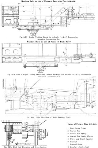
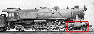
On a steam locomotive, a trailing wheel or trailing axle is generally an unpowered wheel or axle (wheelset) located behind the driving wheels. The axle of the trailing wheels is usually located in a trailing truck. On some large locomotives, a booster engine was mounted on the trailing truck to provide extra tractive effort when starting a heavy train and at low speeds on gradients.

<span class="mw-page-title-main">Co-Co locomotive</span> Locomotive wheel arrangement

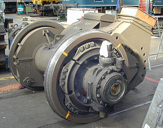
Co-Co is the wheel arrangement for diesel and electric locomotives with two six-wheeled bogies with all axles powered, with a separate traction motor per axle. The equivalent UIC classification (Europe) for this arrangement is Co′Co′, or C-C for AAR.

B-B and Bo-Bo are the Association of American Railroads (AAR) and British classifications of wheel arrangement for railway locomotives with four axles in two individual bogies. They are equivalent to the B′B′ and Bo′Bo′ classifications in the UIC system. The arrangement of two, two-axled, bogies is a common wheel arrangement for modern electric and diesel locomotives.

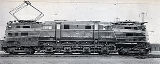
The Pennsylvania Railroad's class P5 comprised 92 mixed-traffic electric locomotives constructed 1931–1935 by the PRR, Westinghouse and General Electric. Although the original intention was that they work mainly passenger trains, the success of the GG1 locomotives meant that the P5 class were mostly used on freight. A single survivor, prototype #4700, is at the National Museum of Transportation in St Louis, Missouri.

<span class="mw-page-title-main">Pennsylvania Railroad class R1</span> American electric locomotive prototype

The Pennsylvania Railroad's class R1 comprised a single prototype electric locomotive constructed in 1934 by the Baldwin Locomotive Works of Philadelphia, Pennsylvania, US, with the electrical equipment by Westinghouse.

In Whyte notation, a 4-6-6-2 is a steam locomotive with four leading wheels in an unpowered bogie at the front of the locomotive followed by two sets of driving wheels with six wheels each, followed by two unpowered trailing wheels at the rear of the locomotive.

<span class="mw-page-title-main">0-8-4T</span> Tank locomotive wheel arrangement

Under the Whyte notation for the classification of steam locomotives, 0-8-4 represents the wheel arrangement of no leading wheels, eight powered and coupled driving wheels on four axles, and four trailing wheels on two axles.

<span class="mw-page-title-main">Co-Bo</span> Locomotive wheel arrangement

Co-Bo or Co′Bo′ is a wheel arrangement in the UIC classification system for railway locomotives. It features two uncoupled bogies. The "Co" bogie has three driven axles and the "Bo" bogie has two.

<span class="mw-page-title-main">Swiss locomotive and railcar classification</span> Classifications of Swiss trains

For more than a century, the Swiss locomotive, multiple unit, motor coach and railcar classification system, in either its original or updated forms, has been used to name and classify the rolling stock operated on the railways of Switzerland. It started out as a uniform system for the classification and naming of all rolling stock, powered and unpowered, but had been replaced and amended by the UIC classification of goods wagons.

Under the French classification system for locomotive wheel arrangements, the system is slightly different for steam and electric/diesel vehicles.

In Whyte notation, a 2-4-6 is a steam locomotive with two unpowered leading wheels followed by four powered driving wheels and six unpowered trailing wheels. This wheel arrangement was only used for tank locomotives; no 2-4-6 tender locomotives were made.

<span class="mw-page-title-main">Leading wheel</span> Unpowered wheel at the front of a locomotive

The leading wheel or leading axle or pilot wheel of a steam locomotive is an unpowered wheel or axle located in front of the driving wheels. The axle or axles of the leading wheels are normally located on a leading truck. Leading wheels are used to help the locomotive negotiate curves and to support the front portion of the boiler.

<span class="mw-page-title-main">1Co+Co1</span>

Under the British and Imperial classification scheme of locomotive axle arrangements 1Co+Co1 is a classification code for a locomotive wheel arrangement of two eight-wheeled bogies with an articulated inter-bogie connection, each with three axles powered by a separate traction motor per axle and with the fourth non-powered axle in an integral leading pony truck to reduce the axle load. The similar 1Co-Co1 classification is in the same axle configuration, but without the inter-bogie connection.

<span class="mw-page-title-main">Rigid-framed electric locomotive</span>

Rigid-framed electric locomotives were some of the first generations of electric locomotive design. When these began the traction motors of these early locomotives, particularly with AC motors, were too large and heavy to be mounted directly to the axles and so were carried on the frame. One of the initial simplest wheel arrangements for a mainline electric locomotive, from around 1900, was the 1′C1′ arrangement, in UIC classification.

References

  1. "Wheel Arrangements". Railway Technical Web Pages. 1 August 2011. Retrieved 1 August 2011.