Related Research Articles
An aircraft is a vehicle that is able to fly by gaining support from the air. It counters the force of gravity by using either static lift or the dynamic lift of an airfoil, or, in a few cases, direct downward thrust from its engines. Common examples of aircraft include airplanes, helicopters, airships, gliders, paramotors, and hot air balloons.

Aeroelasticity is the branch of physics and engineering studying the interactions between the inertial, elastic, and aerodynamic forces occurring while an elastic body is exposed to a fluid flow. The study of aeroelasticity may be broadly classified into two fields: static aeroelasticity dealing with the static or steady state response of an elastic body to a fluid flow, and dynamic aeroelasticity dealing with the body's dynamic response.
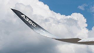
Wingtip devices are intended to improve the efficiency of fixed-wing aircraft by reducing drag. Although there are several types of wing tip devices which function in different manners, their intended effect is always to reduce an aircraft's drag. Wingtip devices can also improve aircraft handling characteristics and enhance safety for following aircraft. Such devices increase the effective aspect ratio of a wing without greatly increasing the wingspan. Extending the span would lower lift-induced drag, but would increase parasitic drag and would require boosting the strength and weight of the wing. At some point, there is no net benefit from further increased span. There may also be operational considerations that limit the allowable wingspan.

A T-tail is an empennage configuration in which the tailplane of an aircraft is mounted to the top of the fin. The arrangement looks like the capital letter T, hence the name. The T-tail differs from the standard configuration in which the tailplane is mounted to the fuselage at the base of the fin.

The mechanical structure of an aircraft is known as the airframe. This structure is typically considered to include the fuselage, undercarriage, empennage and wings, and excludes the propulsion system.

The Tupolev Tu-80 was a Soviet prototype for a longer-ranged version of the Tupolev Tu-4 bomber, an unlicensed, reverse engineered copy of the Boeing B-29 Superfortress. It was cancelled in 1949 in favor of the Tupolev Tu-85 program which offered even more range. The sole prototype was used in various test programs before finally being used as a target.

The Grumman X-29 is an American experimental aircraft that tested a forward-swept wing, canard control surfaces, and other novel aircraft technologies. Funded by NASA, the United States Air Force and DARPA, the X-29 was developed by Grumman, and the two built were flown by NASA and the United States Air Force. The aerodynamic instability of the X-29's airframe required the use of computerized fly-by-wire control. Composite materials were used to control the aeroelastic divergent twisting experienced by forward-swept wings, and to reduce weight. The aircraft first flew in 1984, and two X-29s were flight tested through 1991.

A forward-swept wing or reverse-swept wing is an aircraft wing configuration in which the quarter-chord line of the wing has a forward sweep. Typically, the leading edge also sweeps forward.
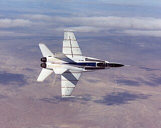
The X-53 Active Aeroelastic Wing (AAW) development program is a completed American research project that was undertaken jointly by the Air Force Research Laboratory (AFRL), Boeing Phantom Works and NASA's Dryden Flight Research Center, where the technology was flight tested on a modified McDonnell Douglas F/A-18 Hornet. Active Aeroelastic Wing Technology is a technology that integrates wing aerodynamics, controls, and structure to harness and control wing aeroelastic twist at high speeds and dynamic pressures. By using multiple leading and trailing edge controls like "aerodynamic tabs", subtle amounts of aeroelastic twist can be controlled to provide large amounts of wing control power, while minimizing maneuver air loads at high wing strain conditions or aerodynamic drag at low wing strain conditions. This program was the first full-scale proof of AAW technology.
An adaptive compliant wing is a wing which is flexible enough for aspects of its shape to be changed in flight. Flexible wings have a number of benefits. Conventional flight control mechanisms operate using hinges, resulting in disruptions to the airflow, vortices, and in some cases, separation of the airflow. These effects contribute to the drag of the aircraft, resulting in less efficiency and higher fuel costs. Flexible aerofoils can manipulate aerodynamic forces with less disruptions to the flow, resulting in less aerodynamic drag and improved fuel economy.

The Northrop Grumman Bat is a medium-altitude unmanned air vehicle originally developed for use by the United States Armed Forces. Designed primarily as an intelligence "ISR" gathering tool, the Bat features 30 lb (14 kg) payload capacity and a 10 ft (3.0 m) wing span.
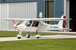
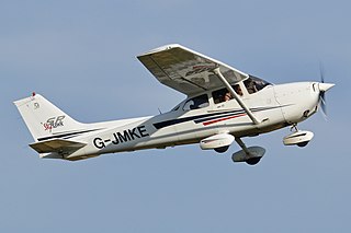
The Ikarus C42 is a two-seat, fixed tricycle gear, general aviation microlight aircraft, manufactured in Germany by Comco Ikarus. It is used primarily for flight training, touring and personal flying.

In aeronautics, a flexible wing is an airfoil or aircraft wing which can deform in flight.
The wingbox of a fixed-wing aircraft is the primary load-carrying structure of the wing, which forms the structural centre of the wings and is also the attachment point for other wing components such as leading edge flaps, swing wings, trailing edge flaps and wing-tip devices. The wingbox continues beyond the visible wing roots and interfaces with the fuselage in the centre wingbox, which forms the structural core of an aircraft.
A crack arrestor is a structural engineering device. Being typically shaped into ring or strip, and composed of a strong material, it serves to contain stress corrosion cracking or fatigue cracking, helping to prevent the catastrophic failure of a device.

The aircraft design process is a loosely defined method used to balance many competing and demanding requirements to produce an aircraft that is strong, lightweight, economical and can carry an adequate payload while being sufficiently reliable to safely fly for the design life of the aircraft. Similar to, but more exacting than, the usual engineering design process, the technique is highly iterative, involving high-level configuration tradeoffs, a mixture of analysis and testing and the detailed examination of the adequacy of every part of the structure. For some types of aircraft, the design process is regulated by civil airworthiness authorities.

The fuel economy in aircraft is the measure of the transport energy efficiency of aircraft. Fuel efficiency is increased with better aerodynamics and by reducing weight, and with improved engine brake-specific fuel consumption and propulsive efficiency or thrust-specific fuel consumption. Endurance and range can be maximized with the optimum airspeed, and economy is better at optimum altitudes, usually higher. An airline efficiency depends on its fleet fuel burn, seating density, air cargo and passenger load factor, while operational procedures like maintenance and routing can save fuel.
The term "smart structures" is commonly used for structures which have the ability to adapt to environmental conditions according to the design requirements. As a rule, the adjustments are designed and performed in order to increase the efficiency or safety of the structure. Combining "smart structures" with the "sophistication" achieved in materials science, information technology, measurement science, sensors, actuators, signal processing, nanotechnology, cybernetics, artificial intelligence, and biomimetics, one can talk about Smart Intelligent Structures. In other words, structures which are able to sense their environment, self-diagnose their condition and adapt in such a way so as to make the design more useful and efficient.
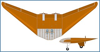
The Horten H.V was a delta-winged, tail-less, twin-engined motor-glider designed and built in the late 1930s and early 1940s by Walter and Reimar Horten in Germany. The H.V aircraft were used for various experimental duties, including: innovative structure, performance, stability and control of flying wing aircraft. The first H.V was the first aircraft to be built using an all composite material structure.

Carlos E. S. Cesnik is a Brazilian-American aerospace engineer, academic, and author. He is the Clarence L. (Kelly) Johnson Collegiate Professor of Aerospace Engineering and the founding Director of the Active Aeroelasticity and Structures Research Laboratory at the University of Michigan. He also directs the Airbus-Michigan Center for Aero-Servo-Elasticity of Very Flexible Aircraft (CASE-VFA).
References
- 1 2 Shirk, M., Hertz, T., Weisshaar, T., "Aeroelastic Tailoring – Theory, Practice, Promise", Journal of Aircraft, Vol. 23, No. 1, pp. 6-18, 1986.
- 1 2 Weisshaar, T., Aircraft Aeroelastic Design and Analysis, 1995
- 1 2 Jutte, Christine; Stanford, Bret K. (1 April 2014). "Aeroelastic Tailoring of Transport Aircraft Wings: State-of-the-Art and Potential Enabling Technologies" . Retrieved 19 December 2021.
 This article incorporates text from this source, which is in the public domain .
 - ↑ Munk, M., "Propeller Containing Diagonally Disposed Fibrous Material," U.S. Patent 2,484,308,1111, Oct. 1949.
| | This article about aircraft engines is a stub. You can help Wikipedia by expanding it. |