Airbag launching

Last updated

Airbag launching refers to a method to launch vessels with marine air bags. It is a methodology for ship launching utilizing air bags. [1]

Contents

The Xiao Qinghe shipyard launched a tank barge with marine airbags on January 20, 1981, and it is known as the first use of marine airbags.

This kind of ship launching method has the advantages of requiring less permanent infrastructure, risk, and cost. The airbags provide support to the hull of the ship, air bags rolling motion take a vessel launch into water, thus it is arguably safer than other options like sideways launching.

Unlike most other launching methods that are fixed infrastructures, airbag launching has relatively less limitations and can be used in versatile ways. [2] It overcomes the disadvantage of fixed track launching in which capacity of shipbuilding and ship repairing is limited by the fixed infrastructures especially in small and medium-sized shipyards. [3]

Airbags

Ship launching airbags are specialized air bags that are used for launching marine vessels. These air bags are made of synthetic-tire-cord reinforcement layers and rubber layers, [4] and are also known as marine airbags. They were invented in 1980.[ citation needed ] The first known use of marine airbags occurred on January 20, 1981, with the launch of a tank barge from the Xiao Qinghe shipyard. From then on, more and more shipyards, especially in China and Southeast Asia, began to use air bags to launch small and medium-sized vessels.

In recent years, higher strength materials have been used in air bag production, allowing them to have much more bearing capacity. Hence, they have begun to be used at the launchings of larger vessels. In October 2011, the successful launch of one vessel with a deadweight tonnage (DWT) of 75000 tonnes set a world record for ship launches utilizing air bags.[ citation needed ] The following year, on June 6, 2012, the ship "He Ming" (IMO number 9657105), with a DWT of 73541 tonnes, total length of 224.8m, breadth of 34m, and depth of 18.5m, also launched successfully using air bags. [5]

Air bag structure

Airbag structure (english).svg

Marine air bags consist of three parts:

  1. Air bag body: the main, cylindrical part of the air bag after being fully inflated with compressed air,
  2. Air bag heads: conical parts connecting the body and the mouths of the air bag, and
  3. Air bag mouths: either metal valves mounted on both ends of the air bag for inflating with air or a valve on one end and a metal lug on the other end used to haul the air bag.

Air bag size and model

Size

The diameter of an air bag varies; sizes include 0.8 m, 1.0 m, 1.2 m, 1.5 m, 1.8 m, etc.

The length of an air bag is specified by the customer when it is manufactured.

Model

Air bags are commonly divided into three to six tire-cord reinforcement layers. There can be more layers, though there are normally less than ten.

Air bag bearing capacity

The maximum load carrying capacity of an air bag, which is the maximum load under which it will suffer no permanent deformation or damage, can be found as follows:

An air bag being compressed.jpg

Let:

be the original diameter of the air bag

be the height of the compressed air bag

be the width of the air bag contacting the ship bottom

be the internal pressure of the air bag

be the effective length of the air bag

Given these variables,

Air bag materials

Ship launching air bags are constructed of synthetic-tire-cord layers; inner and outer rubber layers are sometimes added. All materials used are vulcanized.

Air bag test

Air tightness test: Without carrying any load, fill the air bag till the internal pressure of the air bag reaches rated working pressure. After 1 hour. The pressure loss should be less than 5% of initial pressure.

Bursting test: Fill the air bag with water until the air bag bursts. The water pressure at the time of bursting shall be no less than three times of rated working pressure. [4]

The arrangements of air bags

Launching type

Based on the ship shapes, the ship may be launched, using air bags, by either end launching type or side launching type

End launching type

There are three ways to arrange air bags when using the end launching type. They are (1) linear arrangement (see Figure A.1), (2) staggered arrangement (see Figure A.2), and (3) two-lines arrangement (see Figure A.3). As for which arrangement to use, it will depend on the ship's width and the length of the air bags.

When the ship's width is not greater than the effective length of the air bags, the linear arrangement shall be selected

Air bags linear arrangement.jpg

When the ship's width is greater than the effective length of an air bag and less than the effective length of two air bags, the staggered arrangement can be selected.

Air bags Staggered arrangement.jpg

When the ship's width is greater than the combined effective length of two air bags, or for special ship such as catamaran HSC or split hopper barge, the two lines arrangement shall be selected. The distance between the near ends of two air bags is greater than 0,2 m.

Air bags Two-lines arrangement.jpg

Side launching type

[6]

For small flat-bottom ships, the side launching method may be utilized (see Figure A.4)

Air bags side launching arrangement.jpg

Air bags quantity

Air bags shall meet the requirements of ISO 14409 [4]

According to the weight of the ship being launched, the quantity of the air bags needed for this operation must be calculated in accordance with Formula (1):

where

N is the quantity of air bags used for ship launching;

K1 is a coefficient, in general, K1 ≥ 1,2;

Q is the weight of the ship (ton);

g is acceleration of gravity (m/s2), g = 9,8;

Cb is the block coefficient of the ship being launched;

R is the allowable unit bearing capacity of the air bags (kN/m);

Ld is the contact length between the bottom of the ship and the body of the air bag at the midship section (m).

For ship shifting, 2 to 4 additional air bags shall be made ready and available.

The centre to centre distance between two neighbouring air bags should be less than or equal to that found in Formula (2) and equal to or be greater than that found in Formula (3).

where

L is the actual length of the ship bottom that can make contact with the air bags (m);

N is the quantity of air bags used for ship launching;

k is a coefficient, k = 1 for steel ships, k = 0,8 for wooden, aluminium and glass-fibre-reinforced ships;

D is the nominal diameter of air bags (m).

Slipway

The gradient and the length of the slipway shall be determined according to the size of the ship and the hydrological condition of the area water.

The bearing capacity of the slipway shall be at least twice as strong as the working pressure of air bags.

For ships of more than 3 000 tons of length, more than 120m, the slipway shall be constructed with reinforced concrete and the height difference between the right and left sides shall be less than 20 mm. For ships of more than 1 000 tons but less than or equal to 3 000 tons in weight, or more than 90 m but less than or equal to 120 m in length, the slipway shall be constructed with cement concrete and the height difference between the right and left sides shall be less than 50 mm. For ships of not more than 1 000 tons in weight or not more than 90 m in length, the slipway may be an earthen slope and shall be compacted even by rollers. The height difference between the right and left sides shall be less than 80 mm.

The main slipway shall enable the ship to glide automatically when the ship is off the tow. The auxiliary slipway shall be determined according to the ship type, the water level at time of launching, the diameter of the air bags, and the safety requirements.

Towing arrangement

A windlass shall be used to control the movement of the ship. Tow system that comprises windlass, steel wire rope and pulley set shall be securely fastened to the ground anchor in front of the berth.

In general, a slow windlass shall be selected for ship launching. The veering speed of the windlass shall be 9 m/min to 13 m/min.

The forces of the windlass and the steel wire rope should be calculated carefully by technicians of ship yards or air bags company.

Force component of ship being launched.jpg

Related Research Articles

<span class="mw-page-title-main">Hull (watercraft)</span> Watertight buoyant body of a ship or boat

A hull is the watertight body of a ship, boat, submarine, or flying boat. The hull may open at the top, or it may be fully or partially covered with a deck. Atop the deck may be a deckhouse and other superstructures, such as a funnel, derrick, or mast. The line where the hull meets the water surface is called the waterline.

<span class="mw-page-title-main">Ceremonial ship launching</span> Ceremonial process of transferring a newly built vessel to the water

Ceremonial ship launching involves the performing of ceremonies associated with the process of transferring a vessel to the water. It is a nautical tradition in many cultures, dating back millennia, to accompany the physical process with ceremonies which have been observed as public celebration and a solemn blessing, usually but not always, in association with the launch itself.

<span class="mw-page-title-main">Boundary layer</span> Layer of fluid in the immediate vicinity of a bounding surface

In physics and fluid mechanics, a boundary layer is the thin layer of fluid in the immediate vicinity of a bounding surface formed by the fluid flowing along the surface. The fluid's interaction with the wall induces a no-slip boundary condition. The flow velocity then monotonically increases above the surface until it returns to the bulk flow velocity. The thin layer consisting of fluid whose velocity has not yet returned to the bulk flow velocity is called the velocity boundary layer.

<span class="mw-page-title-main">Lumped-element model</span> Simplification of a physical system into a network of discrete components

The lumped-element model is a simplified representation of a physical system or circuit that assumes all components are concentrated at a single point and their behavior can be described by idealized mathematical models. The lumped-element model simplifies the system or circuit behavior description into a topology. It is useful in electrical systems, mechanical multibody systems, heat transfer, acoustics, etc. This is in contrast to distributed parameter systems or models in which the behaviour is distributed spatially and cannot be considered as localized into discrete entities.

In continuum mechanics, the Froude number is a dimensionless number defined as the ratio of the flow inertia to the external force field. The Froude number is based on the speed–length ratio which he defined as: where u is the local flow velocity, g is the local gravity field, and L is a characteristic length.

<span class="mw-page-title-main">Compressed-air energy storage</span> Method for matching variable production with demand

Compressed-air-energy storage (CAES) is a way to store energy for later use using compressed air. At a utility scale, energy generated during periods of low demand can be released during peak load periods.

<span class="mw-page-title-main">Lifting bag</span> Airtight bag used for underwater buoyant lifting when filled with air

A lifting bag is an item of diving equipment consisting of a robust and air-tight bag with straps, which is used to lift heavy objects underwater by means of the bag's buoyancy. The heavy object can either be moved horizontally underwater by the diver or sent unaccompanied to the surface.

<span class="mw-page-title-main">Pressure vessel</span> Vessel for pressurised gases or liquids

A pressure vessel is a container designed to hold gases or liquids at a pressure substantially different from the ambient pressure.

<span class="mw-page-title-main">Cargo ship</span> Ship or vessel that carries goods and materials

A cargo ship or freighter is a merchant ship that carries cargo, goods, and materials from one port to another. Thousands of cargo carriers ply the world's seas and oceans each year, handling the bulk of international trade. Cargo ships are usually specially designed for the task, often being equipped with cranes and other mechanisms to load and unload, and come in all sizes. Today, they are almost always built of welded steel, and with some exceptions generally have a life expectancy of 25 to 30 years before being scrapped.

<span class="mw-page-title-main">Slipway</span> Shore ramp from which boats or ships can be lowered into or raised out of the water

A slipway, also known as boat ramp or launch or boat deployer, is a ramp on the shore by which ships or boats can be moved to and from the water. They are used for building and repairing ships and boats, and for launching and retrieving small boats on trailers towed by automobiles and flying boats on their undercarriage.

<span class="mw-page-title-main">Compound steam engine</span> Steam engine where steam is expanded in stages

A compound steam engine unit is a type of steam engine where steam is expanded in two or more stages. A typical arrangement for a compound engine is that the steam is first expanded in a high-pressure (HP) cylinder, then having given up heat and losing pressure, it exhausts directly into one or more larger-volume low-pressure (LP) cylinders. Multiple-expansion engines employ additional cylinders, of progressively lower pressure, to extract further energy from the steam.

A sound attenuator, or duct silencer, sound trap, or muffler, is a noise control acoustical treatment of Heating Ventilating and Air-Conditioning (HVAC) ductwork designed to reduce transmission of noise through the ductwork, either from equipment into occupied spaces in a building, or between occupied spaces.

<span class="mw-page-title-main">Bulbous bow</span> Protruding bulb at the front of a ship

A bulbous bow is a streamlined flaring or protruding bulb at the bow of a ship just below the waterline. The flare or bulb modifies the way the water flows around the hull, reducing drag and thus increasing speed, range, fuel efficiency, and stability. Large ships with bulbous bows generally have twelve to fifteen percent better fuel efficiency than similar vessels without them. A bulbous bow also increases the buoyancy of the forward part and hence reduces the pitching of the ship to a small degree.

<span class="mw-page-title-main">Wood drying</span> Also known as seasoning, which is the reduction of the moisture content of wood prior to its use

Wood drying reduces the moisture content of wood before its use. When the drying is done in a kiln, the product is known as kiln-dried timber or lumber, whereas air drying is the more traditional method.

In non ideal fluid dynamics, the Hagen–Poiseuille equation, also known as the Hagen–Poiseuille law, Poiseuille law or Poiseuille equation, is a physical law that gives the pressure drop in an incompressible and Newtonian fluid in laminar flow flowing through a long cylindrical pipe of constant cross section. It can be successfully applied to air flow in lung alveoli, or the flow through a drinking straw or through a hypodermic needle. It was experimentally derived independently by Jean Léonard Marie Poiseuille in 1838 and Gotthilf Heinrich Ludwig Hagen, and published by Hagen in 1839 and then by Poiseuille in 1840–41 and 1846. The theoretical justification of the Poiseuille law was given by George Stokes in 1845.

<span class="mw-page-title-main">Severnaya Verf</span> Shipyard on Gutuevsky Island, Saint Petersburg, Russia

Severnaya Verf is a major shipyard on Gutuevsky Island in Saint Petersburg, Russia, producing naval and civilian ships. It was founded as a branch of the Putilov Plant in the late 1800s. Under the Soviets, the shipyard was generally known as Shipyard No. 190 and reverted to its former name in 1989.

<span class="mw-page-title-main">Vacuum airship</span> Hypothetical airship that is evacuated rather than filled with a lighter-than-air gas

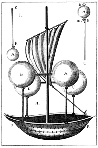
A vacuum airship, also known as a vacuum balloon, is a hypothetical airship that is evacuated rather than filled with a lighter-than-air gas such as hydrogen or helium. First proposed by Italian Jesuit priest Francesco Lana de Terzi in 1670, the vacuum balloon would be the ultimate expression of lifting power per volume displaced.

<span class="mw-page-title-main">Dunnage bag</span> Bags used to secure and stabilize cargo

Dunnage bags, also known as airbags, and inflatable bags, are used to secure and stabilize cargo.

Vertical pressure variation is the variation in pressure as a function of elevation. Depending on the fluid in question and the context being referred to, it may also vary significantly in dimensions perpendicular to elevation as well, and these variations have relevance in the context of pressure gradient force and its effects. However, the vertical variation is especially significant, as it results from the pull of gravity on the fluid; namely, for the same given fluid, a decrease in elevation within it corresponds to a taller column of fluid weighing down on that point.

SS <i>Empress Queen</i>

SS Empress Queen was a steel-hulled paddle steamer, the last of her type ordered by the Isle of Man Steam Packet Company. The Admiralty chartered her in 1915 as a troop ship a role in which she saw service until she ran aground off Bembridge, Isle of Wight, England in 1916 and was subsequently abandoned.

References

  1. ISO 17682-2013 Ships and marine technology — Methodology for ship launching utilizing air bags
  2. "ShipLaunching.org - Ship Repair & Launching Innovation". Shiplaunching.org. Retrieved 2018-08-07.
  3. "Rubber Ship Launching Airbag - Max Groups Marine". Max Groups Marine. Retrieved 2018-08-07.
  4. 1 2 3 ISO14409-Ships and marine technology of Ship launching air bags
  5. "He Ming". MarineTraffic. Retrieved 2018-06-19.
  6. "荣成神飞船舶6200吨成品油轮-SF601下水".