An industrial robot is a robot system used for manufacturing. Industrial robots are automated, programmable and capable of movement on three or more axes.

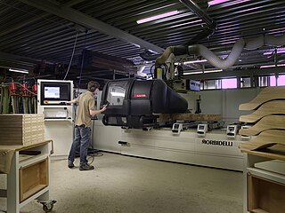
In machining, numerical control, also called computer numerical control (CNC), is the automated control of tools by means of a computer. It is used to operate tools such as drills, lathes, mills, grinders, routers and 3D printers. CNC transforms a piece of material into a specified shape by following coded programmed instructions and without a manual operator directly controlling the machining operation.

A Cartesian coordinate robot is an industrial robot whose three principal axes of control are linear and are at right angles to each other. The three sliding joints correspond to moving the wrist up-down, in-out, back-forth. Among other advantages, this mechanical arrangement simplifies the robot control arm solution. It has high reliability and precision when operating in three-dimensional space. As a robot coordinate system, it is also effective for horizontal travel and for stacking bins.

FANUC is a Japanese group of companies that provide automation products and services such as robotics and computer numerical control wireless systems. These companies are principally FANUC Corporation of Japan, Fanuc America Corporation of Rochester Hills, Michigan, USA, and FANUC Europe Corporation S.A. of Luxembourg.

Computer-integrated manufacturing (CIM) is the manufacturing approach of using computers to control the entire production process. This integration allows individual processes to exchange information with each part. Manufacturing can be faster and less error-prone by the integration of computers. Typically CIM relies on closed-loop control processes based on real-time input from sensors. It is also known as flexible design and manufacturing.

In machining, a metal lathe or metalworking lathe is a large class of lathes designed for precisely machining relatively hard materials. They were originally designed to machine metals; however, with the advent of plastics and other materials, and with their inherent versatility, they are used in a wide range of applications, and a broad range of materials. In machining jargon, where the larger context is already understood, they are usually simply called lathes, or else referred to by more-specific subtype names. These rigid machine tools remove material from a rotating workpiece via the movements of various cutting tools, such as tool bits and drill bits.

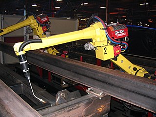
An articulated robot is a robot with rotary joints. Articulated robots can range from simple two-jointed structures to systems with 10 or more interacting joints and materials. They are powered by a variety of means, including electric motors.

A turret lathe is a form of metalworking lathe that is used for repetitive production of duplicate parts, which by the nature of their cutting process are usually interchangeable. It evolved from earlier lathes with the addition of the turret, which is an indexable toolholder that allows multiple cutting operations to be performed, each with a different cutting tool, in easy, rapid succession, with no need for the operator to perform set-up tasks in between or to control the toolpath. The latter is due to the toolpath's being controlled by the machine, either in jig-like fashion, via the mechanical limits placed on it by the turret's slide and stops, or via digitally-directed servomechanisms for computer numerical control lathes.
Lights-out manufacturing is the methodology of fully automating the production of goods at factories and other industrial facilities, such as to require no human presence on-site. Many of these factories are considered to be able to run "with the lights off," but few run exclusively lights-out production. For example, in computer numerical control machining, the presence of human workers is typically required for removing completed parts and setting up tombstones that hold unfinished parts. As the technology necessary for total automation becomes increasingly available, many factories are beginning to use lights-out production between shifts to meet increasing production demand or to save money on labor.

A robotic arm is a type of mechanical arm, usually programmable, with similar functions to a human arm; the arm may be the sum total of the mechanism or may be part of a more complex robot. The links of such a manipulator are connected by joints allowing either rotational motion or translational (linear) displacement. The links of the manipulator can be considered to form a kinematic chain. The terminus of the kinematic chain of the manipulator is called the end effector and it is analogous to the human hand. However, the term "robotic hand" as a synonym of the robotic arm is often proscribed.

An agricultural robot is a robot deployed for agricultural purposes. The main area of application of robots in agriculture today is at the harvesting stage. Emerging applications of robots or drones in agriculture include weed control, cloud seeding, planting seeds, harvesting, environmental monitoring and soil analysis. According to Verified Market Research, the agricultural robots market is expected to reach $11.58 billion by 2025.
A vision-guided robot (VGR) system is basically a robot fitted with one or more cameras used as sensors to provide a secondary feedback signal to the robot controller to more accurately move to a variable target position. VGR is rapidly transforming production processes by enabling robots to be highly adaptable and more easily implemented, while dramatically reducing the cost and complexity of fixed tooling previously associated with the design and set up of robotic cells, whether for material handling, automated assembly, agricultural applications, life sciences, and more.

The Fay automatic lathe was an automatic lathe tailored to cutting workpieces that were mounted on centers. It could also do chucking work. Examples of workpieces included automotive steering knuckles and transmission gears, and such work done on mandrels as flanges, disks, and hubs. The machine tool was developed by F.C. Fay of Philadelphia and improved by Otto A. Schaum. It was originally manufactured by the Fay & Scott Machine Shop. James Hartness acquired manufacturing rights on behalf of the Jones & Lamson Machine Company and manufactured an improved version, developed under the management of Ralph Flanders.
LinuxCNC is a free, open-source Linux software system that implements numerical control capability using general purpose computers to control CNC machines. It's mainly intended to run on PC AMD x86-64 systems. Designed by various volunteer developers at linuxcnc.org, it is typically bundled as an ISO file with a modified version of Debian Linux which provides the required real-time kernel.

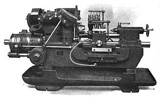
In metalworking and woodworking, an automatic lathe is a lathe with an automatically controlled cutting process. Automatic lathes were first developed in the 1870s and were mechanically controlled. From the advent of NC and CNC in the 1950s, the term automatic lathe has generally been used for only mechanically controlled lathes, although some manufacturers market Swiss-type CNC lathes as 'automatic'.

Milling is the process of machining using rotary cutters to remove material by advancing a cutter into a workpiece. This may be done by varying directions on one or several axes, cutter head speed, and pressure. Milling covers a wide variety of different operations and machines, on scales from small individual parts to large, heavy-duty gang milling operations. It is one of the most commonly used processes for machining custom parts to precise tolerances.
The history of numerical control (NC) began when the automation of machine tools first incorporated concepts of abstractly programmable logic, and it continues today with the ongoing evolution of computer numerical control (CNC) technology.

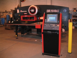
A turret punch or turret press is a type of punch press used for metal forming by punching.
CNC riveting is a CNC process used for obtaining permanent mechanical fastening of geometrical shapes, ranging from simple to complex shapes, such as aircraft fuselages. This is done in a shorter duration of time with a high riveting rate. The process is fast, robust, and is flexible in nature; thus improving its usage and providing reliability to the riveted joint along with the final product quality. CNC riveting can be used for a variety of operations ranging from riveting and fastening belts, skin panels, shear ties, and other internal fuselage components.

A high performance positioning system (HPPS) is a type of positioning system consisting of a piece of electromechanics equipment (e.g. an assembly of linear stages and rotary stages) that is capable of moving an object in a three-dimensional space within a work envelope. Positioning could be done point to point or along a desired path of motion. Position is typically defined in six degrees of freedom, including linear, in an x,y,z cartesian coordinate system, and angular orientation of yaw, pitch, roll. HPPS are used in many manufacturing processes to move an object (tool or part) smoothly and accurately in six degrees of freedom, along a desired path, at a desired orientation, with high acceleration, high deceleration, high velocity and low settling time. It is designed to quickly stop its motion and accurately place the moving object at its desired final position and orientation with minimal jittering.


